
Data Sheet

DMOS Microstepping Driver with Translator
and Overcurrent Protection
A4988
6
Allegro MicroSystems, Inc.
115 Northeast Cutoff
Worcester, Massachusetts 01615-0036 U.S.A.
1.508.853.5000; www.allegromicro.com
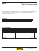
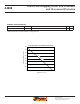
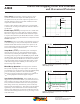
Figure 1. Logic Interface Timing Diagram
STEP
t
A
t
D
t
C
MS1, MS2, MS3,
RESET, or DIR
t
B
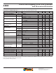
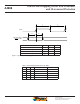
Table 1. Microstepping Resolution Truth Table
Time Duration Symbol Typ. Unit
STEP minimum, HIGH pulse width t
A
1 s
STEP minimum, LOW pulse width t
B
1 s
Setup time, input change to STEP t
C
200 ns
Hold time, input change to STEP t
D
200 ns
MS1 MS2 MS3 Microstep Resolution Excitation Mode
L L L Full Step 2 Phase
H L L Half Step 1-2 Phase
L H L Quarter Step W1-2 Phase
H H L Eighth Step 2W1-2 Phase
H H H Sixteenth Step 4W1-2 Phase