Pololu Maestro Servo Controller User’s Guide © 2001–2019 Pololu Corporation Pololu Maestro Servo Controller User’s Guide https://www.pololu.
Pololu Maestro Servo Controller User’s Guide 1. Overview . . . . . . . . . . . . . . . . . . . . . . . . . 1.a. Micro Maestro Pinout and Components . . . . . . 1.b. Mini Maestro Pinout and Components . . . . . . 1.c. Indicator LEDs . . . . . . . . . . . . . . . . . . . 1.d. Supported Operating Systems . . . . . . . . . . 2. Contacting Pololu . . . . . . . . . . . . . . . . . . . . . 3. Getting Started . . . . . . . . . . . . . . . . . . . . . . 3.a. Installing Windows Drivers and Software . . . . . 3.b.
Pololu Maestro Servo Controller User’s Guide 7.a. Powering the Maestro . . . . . . . . 7.b. Attaching Servos and Peripherals . . 7.c. Connecting to a Microcontroller . . . 8. Writing PC Software to Control the Maestro 9. Maestro Settings Limitations . . . . . . . . 10. Related Resources . . . . . . . . . . . . © 2001–2019 Pololu Corporation . . . . . . . . . . . . . . . . . . . . . . . . . . . . . . . . . . . . . . . . . . . . . . . . . . . . . . . . . . . . . . . . . . . . . . . . . . . . .
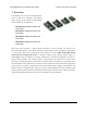
Pololu Maestro Servo Controller User’s Guide © 2001–2019 Pololu Corporation 1. Overview The Maestros are Pololu’s second-generation family of USB servo controllers. The Maestro family consists of four controllers, each available fully assembled or as a partial kit: • Micro Maestro 6 [https://www.pololu.com/ product/1350] • Mini Maestro 12 [https://www.pololu.com/ product/1352] • Mini Maestro 18 [https://www.pololu.com/ product/1354] • Mini Maestro 24 [https://www.pololu.
Pololu Maestro Servo Controller User’s Guide © 2001–2019 Pololu Corporation A free configuration and control program is available for Windows and Linux (see Section 4), making it simple to configure and test the board over USB, create sequences of servo movements for animatronics or walking robots, and write, step through, and run scripts stored in the servo controller.
Pololu Maestro Servo Controller User’s Guide © 2001–2019 Pololu Corporation Features • Three control methods: USB, TTL (5 V) serial, and internal scripting • 0.25μs output pulse width resolution (corresponds to approximately 0.
Pololu Maestro Servo Controller User’s Guide © 2001–2019 Pololu Corporation • Free configuration and control application for Windows and Linux makes it easy to: ◦ Configure and test your controller ◦ Create, run, and save sequences of servo movements for animatronics and walking robots ◦ Write, step through, and run scripts stored in the servo controller The Channel Settings tab in the Maestro Control Center.
Pololu Maestro Servo Controller User’s Guide © 2001–2019 Pololu Corporation single serial receive line without extra components (does not apply to Micro Maestros) ◦ Can function as a general-purpose USB-to-TTL serial adapter for projects controlled from a PC • Board can be powered off of USB or a 5 – 16 V battery, and it makes the regulated 5V available to the user • Upgradable firmware 1.
Pololu Maestro Servo Controller User’s Guide © 2001–2019 Pololu Corporation Maestro Comparison Table Micro Maestro Mini Maestro 12 Mini Maestro 18 Mini Maestro 24 Channels: 6 12 18 24 Analog input channels: 6 12 12 12 Digital input channels: 0 0 6 12 Width: 0.85" (2.16 cm) 1.10" (2.79 cm) 1.10" (2.79 cm) 1.10" (2.79 cm) Length: 1.20" (3.05 cm) 1.42" (3.61 cm) 1.80" (4.57 cm) 2.30" (5.84 cm) Weight(1): 3.0 g 4.2 g 4.9 g 6.
Pololu Maestro Servo Controller User’s Guide © 2001–2019 Pololu Corporation Application Examples • Serial servo controller for multi-servo projects (e.g. robot arms, animatronics, fun-house displays) based on microcontroller boards such as the BASIC Stamp, Orangutan robot controllers [https://www.pololu.
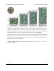
Pololu Maestro Servo Controller User’s Guide © 2001–2019 Pololu Corporation Micro Maestro 6-channel USB servo controller (fully assembled) labeled top view. Note: This section applies to the Micro Maestro servo controller. Please see Section 1.b for Mini Maestro pinout and component information. The Pololu Micro Maestro 6-channel servo controller can connect to a computer’s USB port via a USB A to mini-B cable [https://www.pololu.com/product/130] (not included).
Pololu Maestro Servo Controller User’s Guide © 2001–2019 Pololu Corporation Servo power connections are provided in the upper right corner of the Micro Maestro board. Servo power is passed directly to the servos without going through a regulator, so the only restrictions on your servo power supply are that it must be within the operating range of your servos and provide enough current for your application.
Pololu Maestro Servo Controller User’s Guide © 2001–2019 Pololu Corporation Device > Reset to default settings… in the Maestro Control Center. Micro Maestro 6-channel USB servo controller bottom view with quarter for size reference. The dimensions of the Micro Maestro PCB are 1.2″ × 0.85″. The mounting holes have a diameter of 0.086″and are intended for #2 or M2 screws. The vertical and horizontal distances between the two mounting holes are 0.65″ and 0.575″. The Micro Maestro weighs 3.0 g (0.
Pololu Maestro Servo Controller User’s Guide © 2001–2019 Pololu Corporation Mini Maestro 18-channel USB servo controller (fully assembled) labeled top view. 1.
Pololu Maestro Servo Controller User’s Guide © 2001–2019 Pololu Corporation Mini Maestro 24-channel USB servo controller (fully assembled) labeled top view. Note: This section applies to the Mini Maestro 12, 18, and 24 servo controllers. Please see Section 1.a for Micro Maestro pinout and component information. The Pololu Mini Maestro 12-,18-, and 24-channel servo controllers can connect to a computer’s USB port via a USB A to mini-B cable [https://www.pololu.com/product/130] (not included).
Pololu Maestro Servo Controller User’s Guide © 2001–2019 Pololu Corporation The processor and the servos can have separate power supplies. Processor power must come either from USB or from an external 5–16V power supply connected to the VIN and GND inputs on the left side of the board. It is safe to have an external power supply connected at the same time that USB is connected; in that case the processor will be powered from the external supply.
Pololu Maestro Servo Controller User’s Guide © 2001–2019 Pololu Corporation The signal lines (0, 1, 2, …) are used for sending pulses to servos, controlling digital outputs, and measuring voltages. The total current limit (in or out) for these pins is 200 mA, but when using the on-board regulator the current out is limited to 50 mA (see above.) The RX line is used to receive non-inverted TTL (0–5 V) serial bytes, such as those from microcontroller UARTs.
Pololu Maestro Servo Controller User’s Guide © 2001–2019 Pololu Corporation Bottom view with dimensions (in inches) of Pololu Micro and Mini Maestro servo controllers. The dimensions of the Mini Maestro PCBs are shown in the picture above, along with the Micro Maestro for comparison. The mounting holes have a diameter of 0.086″and are intended for #2 or M2 screws. The vertical and horizontal distances between the two mounting holes are as follows: 1.2″ and 0.5″ for the Mini Maestro 12, 1.58″ and 0.
Pololu Maestro Servo Controller User’s Guide © 2001–2019 Pololu Corporation proportional to the servo period (the amount of time between pulses on a single channel); with a period of 20 ms the flashing occurs approximately once per second.
Pololu Maestro Servo Controller User’s Guide © 2001–2019 Pololu Corporation 2. Contacting Pololu You can check the product page of your particular Maestro model for additional information. We would be delighted to hear from you about any of your projects and about your experience with the Maestro. You can contact us [https://www.pololu.com/contact] directly or post on our forum [http://forum.pololu.com/].
Pololu Maestro Servo Controller User’s Guide © 2001–2019 Pololu Corporation 3. Getting Started 3.a. Installing Windows Drivers and Software If you are using Windows XP, you will need to have Service Pack 3 [https://technet.microsoft.com/en-us/windows/windows-xp-service-pack-3.aspx] installed before installing the drivers for the Maestro. See below for details. Before you connect your Maestro to a computer running Microsoft Windows, you should install its drivers: 1.
Pololu Maestro Servo Controller User’s Guide © 2001–2019 Pololu Corporation necessary drivers. No further action from you is required. Windows XP users: After following the steps above, follow steps 5 through 9 below for each new Maestro you connect to your computer. 5. Connect the device to your computer’s USB port. The Maestro shows up as three devices in one so your XP computer will detect all three of those new devices and display the “Found New Hardware Wizard” three times.
Pololu Maestro Servo Controller User’s Guide © 2001–2019 Pololu Corporation 8. Windows XP will warn you again that the driver has not been tested by Microsoft and recommend that you stop the installation. Click “Continue Anyway”. 9. When you have finished the “Found New Hardware Wizard”, click “Finish”. After that, another wizard will pop up. You will see a total of three wizards when plugging in the Maestro. Follow steps 6-9 for each wizard. 3.
Pololu Maestro Servo Controller User’s Guide © 2001–2019 Pololu Corporation After installing the drivers and plugging the Maestro in via USB, if you go to your computer’s Device Manager, you should see three entries for the Maestro that look like what is shown below: 3.
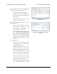
Pololu Maestro Servo Controller User’s Guide © 2001–2019 Pololu Corporation Windows 7 device manager showing the Micro Maestro 6-channel USB servo controller. Windows XP device manager showing the Micro Maestro 6-channel USB servo controller. COM ports After installing the drivers, if you go to your computer’s Device Manager and expand the “Ports (COM & LPT)” list, you should see two COM ports for the Maestro: the Command Port and the TTL Port.
Pololu Maestro Servo Controller User’s Guide © 2001–2019 Pololu Corporation having descriptive names. This can happen if you are using Windows 10 or later and you plugged the Maestro into your computer before installing our drivers for it. In that case, Windows will set up your Maestro using the default Windows serial driver (usbser.inf), and it will display “USB Serial Device” as the name for each port.
Pololu Maestro Servo Controller User’s Guide © 2001–2019 Pololu Corporation The Maestro Control Center running in Ubuntu Linux. You can download the Maestro Control Center and the Maestro command-line utility (UscCmd) for Linux here: • Maestro Servo linux-150116.tar.gz] Controller Linux Software [https://www.pololu.com/file/0J315/maestro- (124k gz) Unzip the tar/gzip archive by running “tar -xzvf” followed by the name of the file. After following the instructions in README.
Pololu Maestro Servo Controller User’s Guide © 2001–2019 Pololu Corporation with are described below. Default Settings • The serial mode is “UART, detect baud rate”; after you send the 0xAA baud rate indication byte, the Maestro will accept TTL-level serial commands on the RX line. • The Pololu Protocol device number is 12, the Mini SSC offset is 0, and serial timeout and CRC are disabled. • All channels are configured as servos, with a minimum pulse with of 992 μs and a maximum pulse width of 2000 μs.
Pololu Maestro Servo Controller User’s Guide © 2001–2019 Pololu Corporation 4. Using the Maestro Control Center The Maestro’s USB interface provides access to all configuration options as well as support for realtime control, feedback, and debugging. The Maestro Control Center is a graphical tool that makes it easy for you to use the USB interface; for almost any project, you will want to start by using the control center to set up and test your Maestro.
Pololu Maestro Servo Controller User’s Guide © 2001–2019 Pololu Corporation reached its target. For more precise control, a target value may also be entered directly into the “Target” input box. The slider is automatically scaled to match the minimum and maximum values specified in the Channel Settings tab, which is described in Section 4.b. For a channel configured as input, the slider, green ball, “Target”, and “Position” display the current value of the input. There is no control available for inputs.
Pololu Maestro Servo Controller User’s Guide Period range © 2001–2019 Pololu Corporation Period On-time resolution resolution 1–1024 4 1 1025–4096 16 4 4097–16384 64 16 The special periods 1024, 4096, and 16384 are not recommended, since 100% duty cycle is not available at these values. If the on time is set equal to the period at one of the special values, the duty cycle will be 0% (a low output). The periods 1020 (47.1 kHz), 4080 (11.7 kHz), and 16320 (2.
Pololu Maestro Servo Controller User’s Guide © 2001–2019 Pololu Corporation A separate row of controls is displayed for each of the Maestro’s channels: Name. Each of the channels may be assigned a name, for your convenience. Channel names are not stored on the device but instead in the system registry on your computer; if you want to use your Maestro on a different computer without losing the names, save a settings file on the old computer and load it into the Maestro with the new one. Mode.
Pololu Maestro Servo Controller User’s Guide © 2001–2019 Pololu Corporation • Ignore specifies that the servo should initially be off, but that its value should not change on error. • Go to specifies a default position for the servo. The servo target will be set to this position on start-up or when an error occurs. Speed. This option specifies the speed of the servo in units of 0.25 μs / (10 ms). For example, with a speed of 4, the position will change by at most 1 μs per 10 ms, or 100.00 μs/s.
Pololu Maestro Servo Controller User’s Guide © 2001–2019 Pololu Corporation to make fewer servos available are to allow a longer maximum pulse length or a shorter period. Period multiplier is an advanced option for the Mini Maestro 12, 18, and 24 that allows a larger period (lower pulse rate) on some of the channels. For example, if you select a period of 3 and a multiplier of 6, you can have some servos run at 3 ms (333 Hz) and the others at 18 ms (55 Hz).
Pololu Maestro Servo Controller User’s Guide © 2001–2019 Pololu Corporation The Sequence tab in the Maestro Control Center. The Sequence tab allows simple motion sequences to be created and played back on the Maestro. A sequence is simply a list of “frames” specifying the positions of each of the servos and a duration (in milliseconds) for each frame. Sequences are stored in the registry of the computer where the sequence was created. Sequences can be copied to the script, which is saved on the Maestro.
Pololu Maestro Servo Controller User’s Guide © 2001–2019 Pololu Corporation The Save Over Current Frame button overwrites the selected frame(s) with the current target values from the Maestro. If the Play in a loop checkbox is checked, sequence playback will loop back to the beginning of the sequence whenever it reaches the end. The Sequence dropdown box along with the Rename, Delete, and New Sequence buttons allow you to create and manage multiple sequences.
Pololu Maestro Servo Controller User’s Guide © 2001–2019 Pololu Corporation • Ctrl+C: Copy selected frames. • Ctrl+V or Shift+Insert: Paste/insert frames from clipboard. • Ctrl+X: Cut selected frames. • Ctrl+Up: Move selected frames up. • Ctrl+Down: Move selected frames down. • Del: Delete selected frames. 4.d. Entering a Script The Script tab in the Maestro Control Center. The Script tab is where you enter a script to be loaded into the Maestro.
Pololu Maestro Servo Controller User’s Guide © 2001–2019 Pololu Corporation the Maestro, one instruction at a time, until a QUIT instruction is reached or an error occurs. In many cases it will be useful to use a loop of some kind to cause a script to run forever. While the script is running, the red “Stop Script” button will be available, and the small pink triangle will jump around your source code, showing you the instruction that is currently being executed.
Pololu Maestro Servo Controller User’s Guide © 2001–2019 Pololu Corporation The Errors tab in the Maestro Control Center. The Errors tab indicates problems that the Maestro has detected while running, either communications errors or errors generated by bugs in a script. Each error corresponds to a bit in the two-byte error register. The red LED will be on as long as any of the bits in the error register are set to 1 (it can also be turned on by the led_on script command).
Pololu Maestro Servo Controller User’s Guide © 2001–2019 Pololu Corporation A hardware-level error that occurs when the UART’s internal buffer fills up. This should not occur during normal operation. • Serial buffer full (bit 2) A firmware-level error that occurs when the firmware’s buffer for bytes received on the RX line is full and a byte from RX has been lost as a result. This error should not occur during normal operation.
Pololu Maestro Servo Controller User’s Guide © 2001–2019 Pololu Corporation Performance Flags The errors tab also shows which performance flags have been set. This feature only applies to the Mini Maestro 12, 18, and 24. The performance flags indicate that the processor missed a deadline for performing a servo control task, and as a result the Maestro’s servo control got slowed down in some way.
Pololu Maestro Servo Controller User’s Guide © 2001–2019 Pololu Corporation servo update routine, causing it to become unresponsive. This bug does not affect the Mini Maestros. Upgrade Instructions You can determine the version of your Maestro’s firmware by running the Maestro Control Center, connecting to a Maestro, and looking at the firmware version number which is displayed in the upper left corner next to the “Connected to” drop-down box. If you do not already have the latest version (1.
Pololu Maestro Servo Controller User’s Guide © 2001–2019 Pololu Corporation if you are sure you want to proceed: click OK. 8. If you are using Windows XP and see a Found New Hardware Wizard window appear, then you should follow steps 6–8 from Section 3.a to get the bootloader’s driver working. 9.
Pololu Maestro Servo Controller User’s Guide © 2001–2019 Pololu Corporation Maestro Control Center will not work, and you will have to resort to a hard bootloader reset. After that, the Maestro will be in bootloader mode and you can restore the Maestro’s correct firmware. 1. To perform a hard bootloader reset, first make sure the Maestro is powered off. It is best if you can just disconnect everything from it. 2.
Pololu Maestro Servo Controller User’s Guide © 2001–2019 Pololu Corporation This might require a few tries. Once it works, you should see the green LED double-blinking, and the Maestro’s bootloader should be visible in your Device Manager (if you are using Windows). Then you can stop shorting together the pads and retry the firmware upgrade procedure in Section 4.f starting at step 7. 4.
Pololu Maestro Servo Controller User’s Guide © 2001–2019 Pololu Corporation 5. Serial Interface 5.a. Serial Settings The Maestro has three different serial interfaces. First, it has the TX and RX lines, which allow the Maestro to send and receive non-inverted, TTL (0 – 5 V) serial bytes (Section 5.b). Secondly, the Maestro shows up as two virtual serial ports on a computer if it is connected via USB. One of these ports is called the Command Port and the other is called the TTL port.
Pololu Maestro Servo Controller User’s Guide © 2001–2019 Pololu Corporation The Serial Settings tab in the Maestro Control Center. The Maestro can be configured to be in one of three basic serial modes: USB Dual Port: In this mode, the Command Port can be used to send commands to the Maestro and receive responses from it. The baud rate you set in your terminal program when opening the Command Port is irrelevant. The TTL Port can be used to send bytes on the TX line and receive bytes on the RX line.
Pololu Maestro Servo Controller User’s Guide © 2001–2019 Pololu Corporation opening the TTL Port determines the baud rate used to receive and send bytes on RX and TX. This allows your computer to control the Maestro and simultaneously use the RX and TX lines as a general purpose serial port that can communicate with other types of TTL serial devices. USB Chained: In this mode, the Command Port is used to both transmit bytes on the TX line and send commands to the Maestro.
Pololu Maestro Servo Controller User’s Guide © 2001–2019 Pololu Corporation Mini SSC offset: This parameter determines which servo numbers the device will respond to in the Mini SSC protocol (see Section 5.e). Timeout: This parameter specifies the duration before which a Serial timeout error will occur. This error can be used as a safety measure to ensure that your servos and digital outputs go back to their default states whenever the software sending commands to the Maestro stops working.
Pololu Maestro Servo Controller User’s Guide © 2001–2019 Pololu Corporation Diagram of a non-inverted TTL serial byte. A non-inverted TTL serial line has a default (non-active) state of high. A transmitted byte begins with a single low “start bit”, followed by the bits of the byte, least-significant bit (LSB) first. Logical ones are transmitted as high (VCC) and logical zeros are transmitted as low (0 V), which is why this format is referred to as “non-inverted” serial.
Pololu Maestro Servo Controller User’s Guide © 2001–2019 Pololu Corporation The Maestro responds to three sub-protocols: Compact Protocol This is the simpler and more compact of the two protocols; it is the protocol you should use if your Maestro is the only device connected to your serial line.
Pololu Maestro Servo Controller User’s Guide © 2001–2019 Pololu Corporation in hex: 0xAA, 0x0C, 0x04, 0x00, 0x70, 0x2E in decimal: 170, 12, 4, 0, 112, 46 Note that 0x04 is the command 0x84 with its most significant bit cleared. Mini SSC Protocol The Maestro also responds to the protocol used by the Mini SSC servo controller. This protocol allows you to control up to 254 different servos by chaining multiple servo controllers together.
Pololu Maestro Servo Controller User’s Guide © 2001–2019 Pololu Corporation transmits in response to serial commands. A detailed account of how cyclic redundancy checking works is beyond the scope of this document, but you can find a wealth of information using Wikipedia [http://en.wikipedia.org/wiki/Cyclic_redundancy_check].
Pololu Maestro Servo Controller User’s Guide © 2001–2019 Pololu Corporation add 7 zeros to the end of the message): CRC-7 Polynomial = [1 0 0 0 1 0 0 1] message = [1 1 0 0 0 0 0 1] [1 0 0 0 0 0 0 0] 0 0 0 0 0 0 0 Steps 3, 4, & 5: _______________________________________________ 1 0 0 0 1 0 0 1 ) 1 1 0 0 0 0 0 1 1 0 0 0 0 0 0 0 0 0 0 0 0 0 0 XOR 1 0 0 0 1 0 0 1 | | | | | | | | | | | | | | | --------------- | | | | | | | | | | | | | | | 1 0 0 1 0 0 0 1 | | | | | | | | | | | | | | shift ----> 1 0 0 0 1 0 0 1
Pololu Maestro Servo Controller User’s Guide © 2001–2019 Pololu Corporation in binary: 10000100, 00000010, 01110000, 00101110 in hex: 0x84, 0x02, 0x70, 0x2E in decimal: 132, 2, 112, 46 Here is some example C code that will generate the correct serial bytes, given an integer “channel” that holds the channel number, an integer “target” that holds the desired target (in units of quarter microseconds if this is a servo channel) and an array called serialBytes: 1 2 3 4 serialBytes[0] serialBytes[1] serialByte
Pololu Maestro Servo Controller User’s Guide © 2001–2019 Pololu Corporation need to send. The second byte specifies the lowest channel number in the block. The subsequent bytes contain the target values for each of the channels, in order by channel number, in the same format as the Set Target command above.
Pololu Maestro Servo Controller User’s Guide © 2001–2019 Pololu Corporation complicated to produce. At the minimum acceleration setting of 1, the servo output takes about 3 seconds to move smoothly from a target of 1 ms to a target of 2 ms. The acceleration setting has no effect on channels configured as inputs or digital outputs.
Pololu Maestro Servo Controller User’s Guide © 2001–2019 Pololu Corporation Note that the position value returned by this command is equal to four times the number displayed in the Position box in the Status tab of the Maestro Control Center.
Pololu Maestro Servo Controller User’s Guide © 2001–2019 Pololu Corporation Go Home Compact protocol: 0xA2 Pololu protocol: 0xAA, device number, 0x22 This command sends all servos and outputs to their home positions, just as if an error had occurred. For servos and outputs set to “Ignore”, the position will be unchanged. Note: For servos marked “Off”, if you execute a Set Target command immediately after Go Home, it will appear that the servo is not obeying speed and acceleration limits.
Pololu Maestro Servo Controller User’s Guide © 2001–2019 Pololu Corporation the stack before starting the subroutine. Since data bytes can only contain 7 bits of data, the parameter must be between 0 and 16383. Get Script Status Compact protocol: 0xAE Pololu protocol: 0xAA, device number, 0x2E Response: 0x00 if the script is running, 0x01 if the script is stopped This command responds with a single byte, either 0 or 1, to indicate whether the script is running (0) or stopped (1).
Pololu Maestro Servo Controller User’s Guide © 2001–2019 Pololu Corporation Daisy chaining serial devices using the Pololu protocol. An optional AND gate is used to join multiple TX lines. The Mini Maestro 12, 18, and 24 have a special input called TXIN that eliminates the need for an external AND gate (the AND gate is built in to the Maestro.) To make a chain of devices using the TXIN input, connect them like this: Daisy chaining serial devices that have a TXIN input.
Pololu Maestro Servo Controller User’s Guide © 2001–2019 Pololu Corporation Receiving serial responses from one of the slave devices on the PC can be achieved by connecting the TX line of that slave device to the RX line of the Maestro. Receiving serial responses from multiple slave devices is more complicated. Each device should only transmit when requested, so if each device is addressed separately, multiple devices will not transmit simultaneously.
Pololu Maestro Servo Controller User’s Guide © 2001–2019 Pololu Corporation This code will work in Windows if compiled with MinGW, but it does not work with the Microsoft C compiler. For Windows-specific example code that works with either compiler, see Section 5.h.2. 5.
Pololu Maestro Servo Controller User’s Guide 1 2 3 4 5 6 7 8 9 10 11 12 13 14 15 16 17 18 19 20 21 22 23 24 25 26 27 28 29 30 31 32 33 34 35 36 37 38 39 40 41 42 43 44 45 46 47 48 49 50 51 52 53 54 55 56 57 58 59 60 61 62 © 2001–2019 Pololu Corporation ? // Uses POSIX functions to send and receive data from a Maestro. // NOTE: The Maestro's serial mode must be set to "USB Dual Port". // NOTE: You must change the 'const char * device' line below. #include #include #include
Pololu Maestro Servo Controller User’s Guide 63 64 65 66 67 68 69 70 71 72 73 74 75 76 77 78 79 80 81 82 83 © 2001–2019 Pololu Corporation #ifdef _WIN32 _setmode(fd, _O_BINARY); #else struct termios options; tcgetattr(fd, &options); options.c_iflag &= ~(INLCR | IGNCR | ICRNL | IXON | IXOFF); options.c_oflag &= ~(ONLCR | OCRNL); options.c_lflag &= ~(ECHO | ECHONL | ICANON | ISIG | IEXTEN); tcsetattr(fd, TCSANOW, &options); #endif int position = maestroGetPosition(fd, 0); printf("Current position is %d.\n"
Pololu Maestro Servo Controller User’s Guide 1 2 3 4 5 6 7 8 9 10 11 12 13 14 15 16 17 18 19 20 21 22 23 24 25 26 27 28 29 30 31 32 33 © 2001–2019 Pololu Corporation #include<18f4550.
Pololu Maestro Servo Controller User’s Guide © 2001–2019 Pololu Corporation byte() { printf "\\x$(printf "%x" $1)" } stty raw -F $DEVICE { byte 0x84 byte $CHANNEL byte $((TARGET & 0x7F)) byte $((TARGET >> 7 & 0x7F)) } > $DEVICE This script can also be run on Windows, but since Windows does not have bash installed by default it is easier to use UscCmd. 5.h.5. Arduino library We provide an Arduino library [https://github.
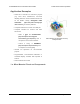
Pololu Maestro Servo Controller User’s Guide © 2001–2019 Pololu Corporation Example setup showing how to control a Maestro with an A-Star Prime or Arduino-compatible board. 5.
Pololu Maestro Servo Controller User’s Guide © 2001–2019 Pololu Corporation 6. The Maestro Scripting Language A script is a sequence of commands that is executed by the Maestro. Commands can set servo targets, speeds, and accelerations, retrieve input values, and perform mathematical computations. Basic control structures – looping and conditionals – are available for use in making complicated scripts.
Pololu Maestro Servo Controller User’s Guide © 2001–2019 Pololu Corporation Note that the PLUS command always decreases the size of the stack by one. It is up to you to make sure that you have enough values on the stack to complete the commands you want to run! Consider a more complicated example: suppose we want to compute the value of (1 – 3) × 4, using the MINUS and MULTIPLY commands. The way to write this computation as a script is “1 3 MINUS 4 TIMES”.
Pololu Maestro Servo Controller User’s Guide 1 2 3 4 5 6 7 8 9 10 10 # start with a 10 on the begin dup # copy the number while # jump to the end 8000 1 servo 500 delay 4000 1 servo 500 delay 1 minus # subtract 1 from repeat © 2001–2019 Pololu Corporation stack ? on the stack - the copy will be consumed by WHILE if the count reaches 0 the number of times remaining Note that BEGIN…WHILE…REPEAT loops are similar to the while loops of many other languages.
Pololu Maestro Servo Controller User’s Guide 1 2 3 4 sub neutral 6000 1 servo 6000 2 servo return © 2001–2019 Pololu Corporation ? Then, whenever you want send these two servos back to neutral, you can just use “neutral” as a command. More advanced subroutines take values off of the stack. For example, the subroutine 1 2 3 sub set_servos 2 servo 1 servo return ? will set channel 2 to the value on the top of the stack and channel 1 to the next value.
Pololu Maestro Servo Controller User’s Guide © 2001–2019 Pololu Corporation Keywords keyword stack effect description BEGIN none marks the beginning of a loop ENDIF none ends a conditional block IF…ENDIF ELSE none begins the alternative block in IF…ELSE…ENDIF GOTO label none goes to the label label (define it with label:) IF -1 enters the conditional block if the argument is true (non-zero) in IF…ENDIF or IF…ELSE…ENDIF REPEAT none marks the end of a loop SUB name none defines a subr
Pololu Maestro Servo Controller User’s Guide © 2001–2019 Pololu Corporation Stack commands command stack effect DEPTH +1 gets the number of numbers on the stack DROP -1 removes the top number from the stack DUP +1 duplicates the top number OVER +1 duplicates the number directly below the top, copying it onto the top PICK -1,+1 takes a number n between 0 and 63, then puts the nth number below the top onto the stack (0 PICK is equivalent to DUP) SWAP a,b → swaps the top two numbers b,a RO
Pololu Maestro Servo Controller User’s Guide command BITWISE_NOT C equivalent ~ © 2001–2019 Pololu Corporation description inverts all of the bits in its argument LOGICAL_NOT ! replaces true by false, false by true NEGATE – replaces x by -x POSITIVE none true if and only if the argument is greater than zero NEGATIVE none true if and only if the argument is less than zero NONZERO none true (1) if and only if the argument is true (non-zero) Mathematical commands (binary) These commands take
Pololu Maestro Servo Controller User’s Guide command C equivalent © 2001–2019 Pololu Corporation description BITWISE_AND & applies the boolean AND function to corresponding bits of the arguments BITWISE_OR | applies the boolean OR function to corresponding bits of the arguments BITWISE_XOR ^ applies the boolean XOR function to corresponding bits of the arguments DIVIDE / divides the arguments EQUALS == true if and only if the arguments are equal GREATER_THAN > true if and only if the fi
Pololu Maestro Servo Controller User’s Guide © 2001–2019 Pololu Corporation Servo, LED, and other output commands command stack effect description SPEED -2 sets the speed of the channel specified by the top element to the value in the second element (see Section 4.b) ACCELERATION -2 sets the acceleration of the channel specified by the top element to the value in the second element (see Section 4.
Pololu Maestro Servo Controller User’s Guide 1 2 3 4 5 6 7 © 2001–2019 Pololu Corporation ? # Blinks the red LED once per second. begin led_on 100 delay led_off 900 delay repeat It is a good idea to try stepping through this script before doing anything further with scripts on the Maestro. In particular, pay attention to how the command “100” puts the number 100 on the stack, and the DELAY command consumes that number.
Pololu Maestro Servo Controller User’s Guide © 2001–2019 Pololu Corporation Note that the servo positions are specified in units of 0.25 μs, so a value of 4000 corresponds to 1 ms. The text after the # is a comment; it does not get programmed on to the device, but it can be useful for making notes about how the program works. Good comments are essential for complicated programs.
Pololu Maestro Servo Controller User’s Guide 1 2 3 4 5 6 7 8 9 10 11 12 13 14 15 # Move servo 0 to five different positions, in a loop. begin 40 frame 50 frame 60 frame 70 frame 80 frame repeat © 2001–2019 Pololu Corporation ? # loads a frame specified in 25 us units sub frame 100 times 0 servo 500 delay return This program is 29 bytes long, with 3 bytes used per position and 14 bytes of overhead.
Pololu Maestro Servo Controller User’s Guide 1 2 3 4 5 6 7 8 9 10 11 12 13 14 15 16 © 2001–2019 Pololu Corporation # Moves servo in a sine wave between 1 and 2 ms.
Pololu Maestro Servo Controller User’s Guide © 2001–2019 Pololu Corporation Using an analog input to control servos An important feature of the Maestro is that it can be used to read inputs from sensors, switches, or other devices. As a simple example, suppose we want to use a potentiometer to control the position of a servo. For this example, connect the potentiometer to form a voltage divider between 5V and 0, with the center tap connected to channel 1.
Pololu Maestro Servo Controller User’s Guide 1 2 3 4 5 6 7 8 9 10 11 12 13 14 15 16 17 18 19 20 21 22 23 24 25 26 27 28 29 30 © 2001–2019 Pololu Corporation # Set the servo to 4000, 6000, or 8000 depending on an analog input, with hysteresis. begin 4000 0 300 servo_range 6000 300 600 servo_range 8000 600 1023 servo_range repeat # usage: servo_range # If the pot is in the range specified by low and # keeps servo 0 at pos until the pot moves out of # range, with hysteresis.
Pololu Maestro Servo Controller User’s Guide 1 2 3 4 5 6 7 8 9 10 11 12 13 14 15 16 17 18 19 20 21 22 23 24 25 26 27 28 29 30 31 32 33 34 35 36 37 38 39 40 41 42 43 44 45 46 47 48 49 50 51 52 53 54 55 56 57 58 59 60 61 62 goto main_loop © 2001–2019 Pololu Corporation # Run the main loop when the script starts (see below). ? # This subroutine returns 1 if the button is pressed, 0 otherwise.
Pololu Maestro Servo Controller User’s Guide 63 © 2001–2019 Pololu Corporation return Just like the sequencing examples above, the script steps through a sequence of frames, but instead of a timed delay between frames, this example waits for a button press. The WAIT_FOR_BUTTON_PRESS subroutine can be used in a variety of different scripts, whenever you want to wait for a button press.
Pololu Maestro Servo Controller User’s Guide 1 2 3 4 5 6 7 8 9 10 11 12 13 14 15 16 17 18 19 20 21 22 23 24 25 26 27 28 29 30 31 32 33 34 35 36 37 38 39 40 41 42 43 44 45 46 47 # When the script is not doing anything else, # this loop will listen for button presses. When a button # is pressed it runs the corresponding sequence.
Pololu Maestro Servo Controller User’s Guide © 2001–2019 Pololu Corporation many seconds or minutes can be accomplished: 1 2 3 4 5 6 7 8 9 10 11 12 13 14 15 16 17 18 19 20 21 # Moves servo 0 back and forth, with a delay of 10 minutes between motions.
Pololu Maestro Servo Controller User’s Guide 1 2 3 4 5 6 7 8 9 10 11 12 13 14 15 16 17 18 19 20 21 22 23 24 25 26 27 28 29 30 31 32 33 34 35 36 begin 1023 0 0 rgb 0 1023 0 rgb 0 0 1023 rgb repeat © 2001–2019 Pololu Corporation ? 500 delay 500 delay 500 delay # red # green # blue # Subroutine for setting the RGB value of a ShiftBrite/ShiftBar.
Pololu Maestro Servo Controller User’s Guide 1 2 3 4 5 6 7 8 9 10 © 2001–2019 Pololu Corporation 100 delay # initial delay to make sure that the other maestro has time to initialize ? begin 127 0 mini_ssc # set servo 0 to position 127, using the mini-SSC command 254 0 mini_ssc # set servo 0 to position 254 repeat sub mini_ssc 0xFF serial_send_byte serial_send_byte serial_send_byte return 6.d.
Pololu Maestro Servo Controller User’s Guide © 2001–2019 Pololu Corporation 7. Wiring Examples This section contains example wiring configurations for the Maestro that demonstrate the different ways it can be connected to your project. Although many of the pictures only show the Micro Maestro, the information in this section applies to all Maestros (unless otherwise noted). 7.a. Powering the Maestro There are several ways to power your Maestro’s processor and the servos it is controlling.
Pololu Maestro Servo Controller User’s Guide © 2001–2019 Pololu Corporation If you connect a power supply to the servo power terminal and connect another power supply to GND/ VIN, then the Maestro’s processor will be powered from the VIN supply while the servos are powered from their own supply. The VIN supply must be within 5–16 V and be capable of supplying at least 30 mA to the Micro Maestro or 50 mA to the Mini Maestro.
Pololu Maestro Servo Controller User’s Guide © 2001–2019 Pololu Corporation input, or as a digital output. This allows the Maestro to control servos, read button presses, read potentiometer positions, drive LEDs, and more. The channels can be controlled from the user script within the Maestro or externally over TTL-level serial or USB. Servo To connect a servo to the Maestro, you must first decide which channel you would like to use.
Pololu Maestro Servo Controller User’s Guide © 2001–2019 Pololu Corporation You can test your input by toggling the button/switch and verifying that the “Position” variable as shown in the Status tab of the Maestro Control Center reflects the state of your button/switch: it should be close to 255.75 when the button/switch is inactive and close to 0 when it is active.
Pololu Maestro Servo Controller User’s Guide © 2001–2019 Pololu Corporation To connect an LED to the Maestro, you should first decide which channel you would like to use. In the Maestro Control Center, under the Channel Settings tab, change that channel to Output mode and click “Apply Settings”. Next, connect the cathode of the LED to GND (any ground pad on the Maestro will suffice because they are all connected).
Pololu Maestro Servo Controller User’s Guide © 2001–2019 Pololu Corporation If you want your microcontroller to have the ability to detect errors from the Maestro using a digital input instead of the serial command, or you want to receive direct feedback from the user script, then connect the ERR line of the Maestro to any general-purpose I/O line of the microcontroller. The ERR line is only available on the Mini Maestro 12-, 18-, and 24-channel servo controllers. See Section 1.
Pololu Maestro Servo Controller User’s Guide © 2001–2019 Pololu Corporation 8. Writing PC Software to Control the Maestro There are two ways to write PC software to control the Maestro: the native USB interface and the virtual serial port. The native USB interface provides more features than the serial port, such as the ability to change configuration parameters and select the Maestro by its serial number. Also, the USB interface allows you to recover more easily from temporary disconnections.
Pololu Maestro Servo Controller User’s Guide © 2001–2019 Pololu Corporation Virtual Serial Ports Almost any programming language is capable of accessing the COM ports created by the Maestro. We recommend the Microsoft .NET framework, which is free to use and contains a SerialPort class that makes it easy to read and write bytes from a serial port. You can download Visual Studio Express (for either C#, C++, or Visual Basic) and write programs that use the SerialPort class to communicate with the Maestro.
Pololu Maestro Servo Controller User’s Guide © 2001–2019 Pololu Corporation 9. Maestro Settings Limitations Mini Maestro serial baud rate limitations On the Mini Maestro 12, 18, and 24, the following baud rates should not be exceeded, or the processor may become overloaded, causing degraded performance. 10–100 Hz 111–250 Hz Serial mode: UART/USB chained* Serial mode: Dual-port 200 kbps 115.2 kbps 333 Hz 115.2 kbps 115.2 kbps 57.6 kbps 57.
Pololu Maestro Servo Controller User’s Guide © 2001–2019 Pololu Corporation On the Mini Maestro 12, 18, and 24, pulse rates of 200–333 Hz put restrictions on the servo pulse lengths. These restrictions apply to all servo channels, even if some are set to a lower pulse rate using the Period multiplier feature. The following tables show allowed minimum and maximum pulse lengths, in microseconds, for a variety of combinations of pulse rates and servo numbers.
Pololu Maestro Servo Controller User’s Guide © 2001–2019 Pololu Corporation Allowed pulse ranges at 200 Hz: Servos Min Max 6 64 3000+ 12 64 3000+ 6/6 384/64 3000+ 18 64 3000+ 12/6 576/64 3000+ 24 24 64 2600 768 3000+ 18/6 768/64 3000+ 9.
Pololu Maestro Servo Controller User’s Guide © 2001–2019 Pololu Corporation 10. Related Resources This section lists resources that might help you use the Maestro. Please note that these resources are of varying quality and most are not tested or supported by Pololu. Tutorials and example code • Sample Project: Simple Hexapod Walker [https://www.pololu.com/docs/0J42] • Obstacle avoider robot [http://forum.pololu.com/viewtopic.php?f=2&t=2756]: This robot features a Maestro as its main controller.
Pololu Maestro Servo Controller User’s Guide © 2001–2019 Pololu Corporation • PHP serial example code [http://forum.pololu.com/viewtopic.php?f=16&t=5951] • MATLAB serial example code [http://forum.pololu.com/ viewtopic.php?f=15&t=5090&p=24142#p24142] • LabVIEW VI for Micro Maestro [http://forum.pololu.com/viewtopic.php?f=23&t=4538] • libusc [https://github.