
User Manual
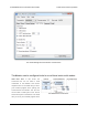

Mini SSC offset: This parameter determines which servo numbers the device will respond to in the
Mini SSC protocol (see Section 5.e).
Timeout: This parameter specifies the duration before which a Serial timeout error will occur. This
error can be used as a safety measure to ensure that your servos and digital outputs go back to their
default states whenever the software sending commands to the Maestro stops working. The serial
timeout error will occur whenever no valid serial commands (or qualifying native USB commands)
are received within the specified timeout period. A timeout period of 0.00 disables the serial timeout
error. The resolution of this parameter is 0.01 s and the maximum value available is 655.35 s. The
native USB commands that qualify correspond to the following methods in the Usc class: setTarget ,
setSpeed , setAcceleration , setPwm , disablePWM , and clearErrors . Running the Maestro Control
Center will not prevent the serial timeout error from occurring, but setting targets in the Status tab or
playing a sequence will.
Never sleep (ignore USB suspend): By default, the Maestro’s processor will go to sleep and stop all
of its operations whenever it detects that it is only powered by USB (no VIN supply) and that the USB
has entered the Suspend State. However, this behavior can be disabled by checking the Never sleep
checkbox.
5.b. TTL Serial
The Maestro’s serial receive line, RX, can receive bytes when connected to a logic-level (0 to 4.0–5 V,
or “TTL”), non-inverted serial signal. The bytes sent to the Maestro on RX can be commands to the
Maestro or an arbitrary stream of data that the Maestro passes on to a computer via the USB port,
depending on which serial mode the Maestro is in (Section 5.a). The voltage on the RX pin should not
go below 0 V and should not exceed 5 V.
The Maestro provides logic-level (0 to 5 V) serial output on its serial transmit line, TX. The bytes sent
by the Maestro on TX can be responses to commands that request information or an arbitrary stream
of data that the Maestro is receiving from a computer via the USB port and passing on, depending
on which Serial Mode the Maestro is in. If you aren’t interested in receiving TTL serial bytes from the
Maestro, you can leave the TX line disconnected.
The serial interface is asynchronous, meaning that the sender and receiver each independently time
the serial bits. Asynchronous TTL serial is available as hardware modules called “UARTs” on many
microcontrollers. Asynchronous serial output can also be “bit-banged” by a standard digital output line
under software control.
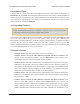
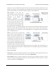
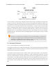
The data format is 8 data bits, one stop bit, with no parity, which is often expressed as 8-N-1. The
diagram below depicts a typical asynchronous, non-inverted TTL serial byte:
Pololu Maestro Servo Controller User’s Guide © 2001–2019 Pololu Corporation
5. Serial Interface Page 49 of 102