
User Manual


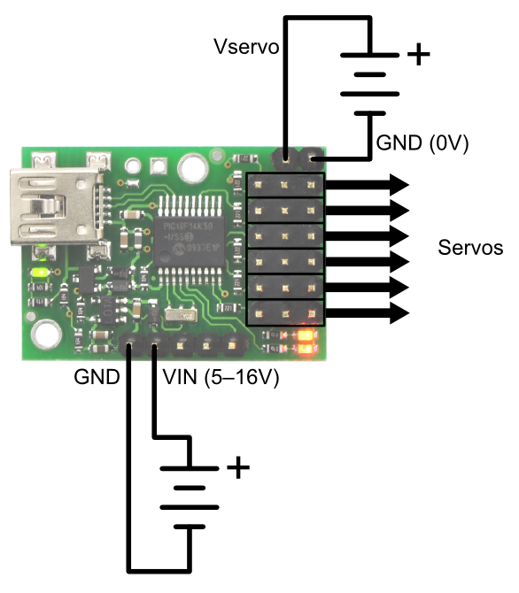
The Micro Maestro’s processor and servos
can be powered separately.
The Micro Maestro’s processor and servos
can be powered from a single 5–16V supply
if you connect the positive servo power rail
to VIN.
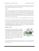
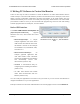
If you connect a power supply to the servo power
terminal and connect another power supply to GND/
VIN, then the Maestro’s processor will be powered
from the VIN supply while the servos are powered
from their own supply. The VIN supply must be within
5–16 V and be capable of supplying at least 30 mA to
the Micro Maestro or 50 mA to the Mini Maestro. The
servo power supply must output a voltage within the
servos’ respective operating ranges and must be
capable of supplying all the current that the servos will
draw.
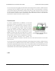
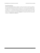
One power supply
If you connect a single power supply to VIN and the
servo power terminal, then the Maestro’s processor
and the servos will be powered from that supply. The
supply must be within 5–16 V and be within the
servos’ respective operating ranges and must be
capable of supplying all the current that the servos will
draw.
On the Micro Maestro 6-channel servo controller, one
way to do the wiring for this configuration is to add a
wire between the servo power rail and the VIN line.
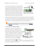
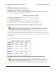
On the Mini Maestro 12-, 18-, and 24-channel servo
controllers, the recommended way to do the wiring for
this configuration is to connect your power supply to
the dedicated servo power pins in the corner of the
board and use the included blue shorting block to connect the pins labeled “VSRV=VIN”.
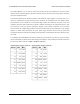
7.b. Attaching Servos and Peripherals
On the Maestro, any of the channels can be used as RC servo pulse output, as an analog/digital
Pololu Maestro Servo Controller User’s Guide © 2001–2019 Pololu Corporation
7. Wiring Examples Page 91 of 102