
User Manual

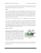
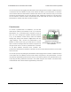
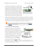
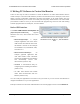
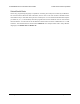
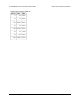

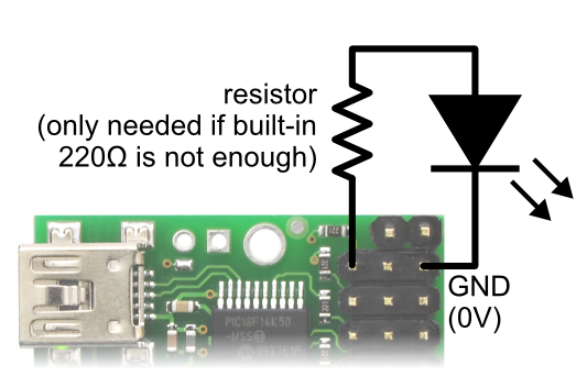
Diagram for connecting an LED to
the Micro Maestro servo controller.
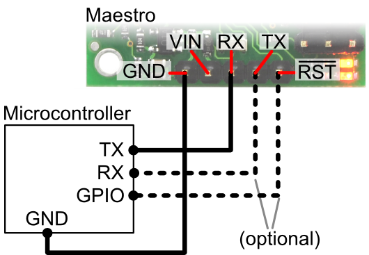
Diagram showing how to connect the
Micro Maestro servo controller to a
microcontroller.
To connect an LED to the Maestro, you should first decide
which channel you would like to use. In the Maestro Control
Center, under the Channel Settings tab, change that channel
to Output mode and click “Apply Settings”. Next, connect the
cathode of the LED to GND (any ground pad on the Maestro
will suffice because they are all connected). Then connect the
anode of the LED to the channel’s signal line (through a
resistor is needed). The signal line has a 220 ohm resistor for
protection, which means you can connect most LEDs directly
to the signal line. However, you should read your LED’s
datasheet to make sure, and add your own resistor if needed.
You can test your LED by setting the “target” of the LED channel in the Status tab of the Maestro
Control Center. The LED should be on if you set the target to be greater than or equal to 1500 μs and
off otherwise. You can control the LED in your script using the SERVO command or over serial using
the “Set Target” command. These commands take arguments in units of quarter-microseconds, so the
LED should be on if you send a number greater than or equal to 6000 and off otherwise.
The total current you can safely draw from the signal lines is limited. See Section 1.a
and Section 1.b for more information.
7.c. Connecting to a Microcontroller
The Maestro can accept TTL serial commands from a
microcontroller. To connect the microcontroller to the
Maestro, you should first connect the ground line of the
microcontroller to the ground line of the Maestro. Then
connect the TX (serial transmit) line of the microcontroller
to the RX line of the Maestro so that the microcontroller
can send commands. If you need to receive serial
responses from the Maestro, then you will need to
connect the RX (serial receive) line of the microcontroller
to the Maestro’s TX line. For more information on the
different serial modes and commands, see Section 5.
If you want your microcontroller to have the ability to
reset the Maestro, then connect the RST line of the Maestro to any general-purpose I/O line of the
microcontroller. You should have the I/O line tri-stated or at 5 V when you want the Maestro to run and
drive it low (0 V) temporarily to reset the Maestro.
Pololu Maestro Servo Controller User’s Guide © 2001–2019 Pololu Corporation
7. Wiring Examples Page 94 of 102