
User Manual
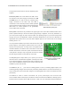
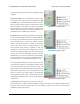

Micro Maestro power pins.
Micro Maestro configured to use
a single power supply for both
board and servos.
The processor and the servos can have separate power
supplies.
Processor power must come either from USB or from
an external 5–16V power supply connected to the VIN
and GND inputs. It is safe to have an external power
supply connected at the same time that USB is
connected; in such cases the processor will be powered
from the external supply. Note that if the external supply
falls below 5 V, correct operation is not guaranteed,
even if USB is also connected.
Servo power connections are provided in the upper right corner of the Micro Maestro board. Servo
power is passed directly to the servos without going through a regulator, so the only restrictions on
your servo power supply are that it must be within the operating range of your servos and provide
enough current for your application. Please consult the datasheets for your servos to determine an
appropriate servo power source, and note that a ballpark figure for the current draw of an average
straining servo is 1 A.
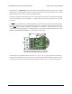
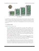
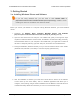
You can power the Maestro’s processor and servos from a single
power supply by connecting the positive power line to both VIN
and the servo power ports. An easy way to accomplish this on
the Micro Maestro is to solder a wire on the bottom of the board
between VIN and one of the servo power connections as shown
in the picture to the right. Only one ground connection is needed
because all ground pins on the board are connected.
The 5V (out) power output allows you to power your own 5V
devices from the on-board 50mA regulator or directly from USB.
The on-board regulator is used whenever VIN is powered; in this
case, since the Maestro requires 30 mA, there is about 20 mA
available to power other devices.
The SIG lines (0, 1, 2, …) are used for sending pulses to servos, controlling digital outputs, and
measuring analog voltages. These lines are protected by 220Ω resistors. The total current limit (in or
out) for these pins is 60 mA, but when using the on-board regulator the current out is limited to 20 mA
(see above.)
The RX line is used to receive non-inverted TTL (0–5 V) serial bytes, such as those from
microcontroller UARTs. These bytes can either be serial commands for the Maestro, arbitrary bytes to
send back to the computer via the USB connection, or both. For more information about the Maestro’s
Pololu Maestro Servo Controller User’s Guide © 2001–2017 Pololu Corporation
1. Overview Page 11 of 99