
User Manual
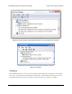
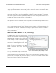

The PWM Output control in the Status tab in the
Maestro Control Center (only available on the
Mini Maestro 12, 18, and 24).
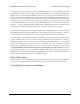
reached its target. For more precise control, a target value may also be entered directly into the
“Target” input box. The slider is automatically scaled to match the minimum and maximum values
specified in the Channel Settings tab, which is described in Section 4.b.
For a channel configured as input, the slider, green ball, “Target”, and “Position” display the current
value of the input. There is no control available for inputs. The inputs on channels 0–11 are analog:
their values range from 0 to 255.75, representing voltages from 0 to 5 V. The inputs on channels 12–23
are digital: their values are either exactly 0 or exactly 255.75.
The “Speed” and “Acceleration” inputs allow the speed and acceleration of individual servo channels
to be adjusted in real time. The default values are specified in the Channel Settings tab, but it can be
useful to adjust them here for fine-tuning.
All of the controls on this tab always display the current values as reported by the Maestro itself, so
they are useful for monitoring the actions caused by another program or device. For example, if a
microcontroller uses the TTL serial interface to change the speed of servo channel 2 to a value of
10, this value will be displayed immediately in the corresponding input, even if something else was
formerly entered there.
PWM Output (Mini Maestro 12, 18, and 24 only)
On the Mini Maestro 12, 18, and 24, one of the
channels may be used as a general-purpose
PWM output with a frequency from 2.93 kHz to
12 MHz and up to 10 bits of resolution. This
could be used, for example, as an input to a
motor driver or for LED brightness control. The
PWM output is on channel 8 for the Mini
Maestro 12 and on channel 12 for the Mini
Maestro 18 and 24. This channel must be
configured as an output for PWM to be
available.
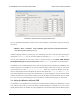
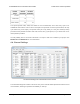
You may use the PWM Output control at the
bottom of the Status tab to test out PWM, by
checking the checkbox and entering specific values for the on time and period, in units of 1/48 μs. A
period of 4800, for example, will generate a frequency of 10 kHz. The resolution on these values
depends on the period as shown in the table below:
Pololu Maestro Servo Controller User’s Guide © 2001–2017 Pololu Corporation
4. Using the Maestro Control Center Page 29 of 99