
User Manual


CRC for that packet. If this CRC byte is incorrect, the Maestro will set the Serial CRC error bit in
the error register and ignore the command. The Maestro does not append a CRC byte to the data it
transmits in response to serial commands.
A detailed account of how cyclic redundancy checking works is beyond the scope of this document, but
you can find a wealth of information using Wikipedia [http://en.wikipedia.org/wiki/Cyclic_redundancy_check].
The CRC computation is basically a carryless long division of a CRC “polynomial”, 0x91, into your
message (expressed as a continuous stream of bits), where all you care about is the remainder. The
Maestro uses CRC-7, which means it uses an 8-bit polynomial and, as a result, produces a 7-bit
remainder. This remainder is the lower 7 bits of the CRC byte you tack onto the end of your command
packets.
The CRC implemented on the Maestro is the same as the one on the jrk
[https://www.pololu.com/product/1392] and qik [https://www.pololu.com/product/1110] motor
controller but differs from that on the TReX [https://www.pololu.com/product/777] motor
controller. Instead of being done MSB first, the computation is performed LSB first to
match the order in which the bits are transmitted over the serial line. In standard binary
notation, the number 0x91 is written as 10010001. However, the bits are transmitted
in this order: 1, 0, 0, 0, 1, 0, 0, 1, so we will write it as 10001001 to carry out the
computation below.
The CRC-7 algorithm is as follows:
1. Express your 8-bit CRC-7 polynomial and message in binary, LSB first. The polynomial 0x91
is written as 10001001.
2. Add 7 zeros to the end of your message.
3. Write your CRC-7 polynomial underneath the message so that the LSB of your polynomial is
directly below the LSB of your message.
4. If the LSB of your CRC-7 is aligned under a 1, XOR the CRC-7 with the message to get a
new message; if the LSB of your CRC-7 is aligned under a 0, do nothing.
5. Shift your CRC-7 right one bit. If all 8 bits of your CRC-7 polynomial still line up underneath
message bits, go back to step 4.
6. What’s left of your message is now your CRC-7 result (transmit these seven bits as your CRC
byte when talking to the Maestro with CRC enabled).
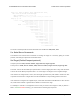
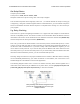
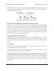
If you have never encountered CRCs before, this probably sounds a lot more complicated than it really
is. The following example shows that the CRC-7 calculation is not that difficult. For the example, we
will use a two-byte sequence: 0x83, 0x01.
Pololu Maestro Servo Controller User’s Guide © 2001–2017 Pololu Corporation
5. Serial Interface Page 52 of 99