
User Manual


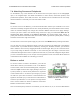

Diagram for connecting a button or
switch to the Micro Maestro Servo
Controller.
7.b. Attaching Servos and Peripherals
On the Maestro, any of the channels can be used as RC servo pulse output, as an analog/digital
input, or as a digital output. This allows the Maestro to control servos, read button presses, read
potentiometer positions, drive LEDs, and more. The channels can be controlled from the user script
within the Maestro or externally over TTL-level serial or USB.
Servo
To connect a servo to the Maestro, you must first decide which channel you would like to use. If the
channel is not already configured to be in servo mode (the default), then in the Maestro Control Center,
under the Channel Settings tab, change that channel to Servo mode and click “Apply Settings”.
Connect your servo cable to the channel, being careful not to plug it in backwards. Make sure to
connect your servo correctly, or it might be destroyed. The signal (usually white, orange, or
yellow) wire should be toward the inside of the board, and the ground wire (usually black or brown)
should be closest to the edge of the board.
You will need to connect a DC power supply for your servos. See Section 7.a for powering information.
You can test your servo by setting the target of the servo channel in the Status tab of the Maestro
Control Center. If you enable the servo channel by checking the “Enabled” checkbox, you should be
able to make the servo move by dragging the slider bar left and right. Now you can control the servos
in your script using the SERVO command, or over serial using the “Set Target” command. These
commands take arguments in units of quarter-microseconds, so you should multiply the Target values
you see in the Status tab by four to compute correct arguments to these commands. More advanced
commands are also available for controlling your servos.
Button or switch
To connect a button or switch to the Maestro, you must first
decide which channel you would like to use. In the Maestro
Control Center, under the Channel Settings tab, change that
channel to Input mode and click “Apply Settings”. Next, wire
a pull-up resistor (1–100 kilo-ohms) between the signal line
of that channel and 5 V so that the input is high (5 V) when
the switch is open. Wire the button or switch between the
signal line and GND (0 V) so that when the button/switch is
active the input will fall to 0 V. The picture to the right shows
how to connect a button or switch to channel 0 on the Micro
Maestro 6-channel servo controller.
Note: An external pull-up resistor is not needed if you use channel 18, 19, or 20 on the Mini Maestro
Pololu Maestro Servo Controller User’s Guide © 2001–2017 Pololu Corporation
7. Wiring Examples Page 90 of 99