Pololu Zumo Shield for Arduino User's Guide © 2001–2013 Pololu Corporation Pololu Zumo Shield for Arduino User's Guide 1. Overview . . . . . . . . . . . . . . . . . . . . . . . . . . . . . . 1.a. Contacting Pololu . . . . . . . . . . . . . . . . . . . . . . 1.b. Included components . . . . . . . . . . . . . . . . . . . . 2. Assembly . . . . . . . . . . . . . . . . . . . . . . . . . . . . . . 2.a. What you will need . . . . . . . . . . . . . . . . . . . . . 2.b. Assembling the Zumo Shield and chassis . .
Pololu Zumo Shield for Arduino User's Guide © 2001–2013 Pololu Corporation 1. Overview The Zumo Shield provides a convenient interface between our Zumo chassis [http://www.pololu.com/catalog/product/ 1418] and an Arduino Uno [http://www.pololu.com/catalog/product/2191] or Leonardo [http://www.pololu.com/catalog/ product/2192] (it is not compatible with the Arduino Mega or Due, but it can be used with older Arduinos that have the same form factor as the Uno, such as the Duemilanove).
Pololu Zumo Shield for Arduino User's Guide © 2001–2013 Pololu Corporation 1.a. Contacting Pololu We would be delighted to hear from you about your experiences with the Zumo Shield for Arduino [http://www.pololu.com/catalog/product/2504] or Zumo robot kit for Arduino [http://www.pololu.com/catalog/product/2505]. If you need technical support or have any feedback you would like to share, you can contact us [http://www.pololu.com/contact] directly or post on our forum [http://forum.pololu.com/viewforum.
Pololu Zumo Shield for Arduino User's Guide © 2001–2013 Pololu Corporation • Zumo chassis kit [http://www.pololu.com/catalog/ product/1418], which includes: ◦ Zumo chassis main body ◦ 1/16″ black acrylic mounting plate (not used with the Zumo Shield) ◦ Two drive sprockets ◦ Two idler sprockets ◦ Two 22-tooth silicone tracks ◦ Two shoulder bolts with washers and M3 nuts ◦ Four 1/4″ #2-56 screws and nuts ◦ Battery terminals • Basic sumo blade for Zumo chassis [http://www.pololu.
Pololu Zumo Shield for Arduino User's Guide © 2001–2013 Pololu Corporation 2. Assembly 2.a. What you will need The Zumo Shield is designed to be mounted on a Zumo chassis kit [http://www.pololu.com/catalog/product/1418], which is included (along with a Zumo blade [http://www.pololu.com/catalog/product/1410]) if you have a Zumo robot kit for Arduino [http://www.pololu.com/catalog/product/2505].
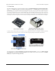
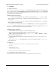
Pololu Zumo Shield for Arduino User's Guide © 2001–2013 Pololu Corporation Through-hole parts 1. Solder the included throughhole components to the shield: ◦ power switch ◦ reset pushbutton ◦ user pushbutton ◦ buzzer ◦ charging connector (1×2-pin female header) 2. On the bottom of the board, trim any leads longer than 1/16″ (the thickness of the spacer plate) so they do not prevent the shield from sitting flat on the spacer plate and chassis. Arduino headers 3.
Pololu Zumo Shield for Arduino User's Guide © 2001–2013 Pololu Corporation 4. On the bottom of the board, trim the four Arduino header pins closest to the front of the board on each side to prevent them from contacting the motor housings. If you think there is a chance these pins might still touch the motor cases, you can put some electrical tape on the motors to act as insulation. Jumpers and additional connections 5.
Pololu Zumo Shield for Arduino User's Guide © 2001–2013 Pololu Corporation Instead of making a wire connection, you can solder a 1×3 male header to the buzzer jumper holes to allow the use of a shorting block for connecting the buzzer. You can also use male headers and shorting blocks for the battery level jumper and compass jumpers if you have an Arduino Leonardo or an Arduino Uno with an SMD (surface mount) microcontroller.
Pololu Zumo Shield for Arduino User's Guide © 2001–2013 Pololu Corporation reasonably quick/efficient with this soldering; if the first attempt does not go well, remove the soldering iron and let the motor cool for a few seconds before trying again. Each motor’s positive terminal is indicated by a plus sign (+) in the black plastic end of the motor, visible at the bottom of the picture above.
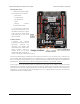
Pololu Zumo Shield for Arduino User's Guide © 2001–2013 Pololu Corporation Chassis and shield To assemble the chassis with the Zumo Shield, you should use the two-piece acrylic spacer plate that is included with the shield. You will not need the one-piece mounting plate that is included with the Zumo chassis. 10. Place an M3 nut in each of the two side slots near the rear of the chassis. The slots are sized so that nuts will not be able to rotate within them.
Pololu Zumo Shield for Arduino User's Guide © 2001–2013 Pololu Corporation If you are also adding a basic sumo blade, you can either mount it now or add it later after you are done soldering the motors and battery contacts. (Note: If you intend to solder anything to the front expansion area of the shield, such as a Zumo reflectance sensor array, you will have more room to work if you do the soldering before adding the sumo blade.
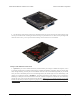
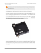
Pololu Zumo Shield for Arduino User's Guide © 2001–2013 Pololu Corporation Battery contacts 15. Turn the chassis over and install the battery terminal contacts as shown in the picture below. Note that the two individual contacts should be inserted into the chassis so that their solder tabs protrude through the holes in the top of the chassis. 2.
Pololu Zumo Shield for Arduino User's Guide © 2001–2013 Pololu Corporation 16. Solder the two individual contacts to the shield from the top. You might want to temporarily tape the contacts inside the chassis to hold them in place while you solder them, or you can use a battery to temporarily hold them in place while you solder. Note that the battery might act as a heat sink, making it more difficult to solder or requiring a higher soldering iron temperature.
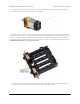
Pololu Zumo Shield for Arduino User's Guide © 2001–2013 Pololu Corporation 19. Press the output shafts of the motors into the drive sprockets, with the “teeth” of the sprockets facing the motor. The end of the gearbox shaft should end up flush with the outside of the sprocket. A good way to accomplish this is to set the wheel on a table top and press the motor shaft into the wheel until it contacts the table. 20.
Pololu Zumo Shield for Arduino User's Guide © 2001–2013 Pololu Corporation Disassembly If you later decide you want to solder additional parts to the Zumo Shield, it is possible to remove it from the chassis with some careful effort. 1. Remove the tracks from the chassis and carefully pull the drive sprockets off the motors. 2. Remove the battery cover and batteries from the chassis. 3. Unscrew all four sets of machine screws and nuts holding the shield to the chassis. 2.
Pololu Zumo Shield for Arduino User's Guide © 2001–2013 Pololu Corporation 4. Squeeze the negative battery terminal spring and gently ease both battery terminals out through the holes in the chassis. The motors will stay attached to the shield as it separates from the chassis. 5. Carefully bend both motors away from the shield to allow the front piece of the spacer plate to be removed. You can reassemble the Zumo afterwards by following this procedure in reverse.
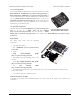
Pololu Zumo Shield for Arduino User's Guide © 2001–2013 Pololu Corporation Assembling the sensor array The Zumo reflectance sensor array ships with all of the components you need to connect it to a Zumo shield: • sensor array PCB with the surface-mount parts pre-populated • 2×12 extended 0.1″ male header (will be soldered to sensor PCB) • 2×12 0.1″ female header (will be soldered to Zumo shield) • 1×3 0.1″ straight male header (optionally soldered to sensor PCB) • 1×3 0.
Pololu Zumo Shield for Arduino User's Guide © 2001–2013 Pololu Corporation The extended 2×12 male header strip should be mounted to the sensor array PCB on the opposite side from the components.
Pololu Zumo Shield for Arduino User's Guide © 2001–2013 Pololu Corporation The reflectance sensor array features two visible (red) LEDs in series with the IR emitter LEDs, so you can use the red LEDs to tell when the emitters are on and off. Array pinout The Zumo reflectance sensor array gets all the necessary power and I/O connections from the 12 header pins that are circled on the silkscreen: The default I/O connections are to pins that are otherwise unused by the Zumo shield.
Pololu Zumo Shield for Arduino User's Guide © 2001–2013 Pololu Corporation Disabling or remapping sensors Many applications do not require all six reflectance sensors, and you might want additional I/O lines for other things (e.g. obstacle detectors). In such cases, you can disable specific sensors and free up their associated I/O lines. The array PCB has six pairs of through holes, each of which corresponds to a different sensor. The order of the pairs matches the order of the sensors.
Pololu Zumo Shield for Arduino User's Guide © 2001–2013 Pololu Corporation Now you effectively have a four-sensor array and analog pins A2 and A3 are available for general-purpose use. To configure the ZumoReflectanceSensorArray library to use this new configuration, call init with these arguments: byte pins[] = {4, 11, A0, 5}; reflectanceSensors.
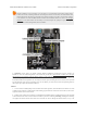
Pololu Zumo Shield for Arduino User's Guide © 2001–2013 Pololu Corporation 3. The Zumo Shield in detail 3.a. Features and components The main features of the Zumo Shield are labeled in this diagram: Power The Zumo chassis has an internal compartment for four AA batteries. We recommend using rechargeable AA NiMH cells [http://www.pololu.com/catalog/product/1003], which results in a nominal voltage of 4.8 V (1.2 V per cell). You can also use alkaline cells, which would nominally give you 6V.
Pololu Zumo Shield for Arduino User's Guide © 2001–2013 Pololu Corporation Warning: When powering the Arduino from the Zumo Shield, you must never connect a different power supply to the Arduino’s VIN pin or plug a power supply into the Arduino’s power jack, as doing so will create a short between the shield’s power supply and the Arduino’s power supply that could permanently damage both the Arduino and the Zumo Shield.
Pololu Zumo Shield for Arduino User's Guide © 2001–2013 Pololu Corporation BZ on the shield; if you alternate between driving it high and low at a given frequency, the buzzer will produce sound at that frequency. The ZumoBuzzer library [http://www.pololu.com/docs/0J57/6] uses hardware PWM to play notes on the buzzer, with digital pin 3 (OC2B) on an Arduino Uno or an older Arduino, or with digital pin 6 (OC4D) on an Arduino Leonardo.
Pololu Zumo Shield for Arduino User's Guide © 2001–2013 Pololu Corporation If you use an Arduino Uno R2 or an older Arduino, which lack separate I²C pins, the SDA and SCL pins on the Zumo Shield will not be connected to anything. To use an I²C device on those pins, you can connect SDA to A4 and SCL to A5 yourself by bridging across those two sets of pins in the front expansion area. Section 3.c further explains the I²C lines and the jumpers connecting them to the onboard compass module.
Pololu Zumo Shield for Arduino User's Guide © 2001–2013 Pololu Corporation The divider outputs a voltage equal to two-thirds of the battery voltage, which will always be safely below the Arduino’s maximum analog input voltage of 5 V. For example, at a battery voltage of 4.8 V, analog pin 1 will be at a level of 3.2 V. Using Arduino’s analogRead() function, where 5 V is read as a value of 1023, 3.2 V is read as a value of 655.
Pololu Zumo Shield for Arduino User's Guide © 2001–2013 Pololu Corporation Level shifters built into the shield allow the LSM303DLHC, which operates at 3.3 V, to be connected to the 5 V logic level pins of the Arduino. The LSM303, level shifters, and I²C pull-up resistors are connected to the SCL and SDA pins on the Zumo Shield by default, but they can be disconnected by cutting traces to allow those pins to be used for other purposes.
Pololu Zumo Shield for Arduino User's Guide © 2001–2013 Pololu Corporation 4. Schematic diagrams Schematic diagrams of the Zumo Shield are available as a downloadable PDF: Zumo Shield schematic diagrams [http://www.pololu.com/file/download/zumo_shield_schematic.pdf?file_id=0J591] (121k pdf). 4.
Pololu Zumo Shield for Arduino User's Guide © 2001–2013 Pololu Corporation 5.
Pololu Zumo Shield for Arduino User's Guide © 2001–2013 Pololu Corporation 6. Zumo Shield Arduino Libraries Our Zumo Shield Libraries make it easy to get started writing Arduino sketches to control your Zumo. A link to download the library and installation instructions can be found on the libraries’ github page [https://github.com/ pololu/zumo-shield-arduino].
Pololu Zumo Shield for Arduino User's Guide © 2001–2013 Pololu Corporation category/123]. Since the Zumo reflectance sensor array [http://www.pololu.com/catalog/product/1419] has the same interface as the QTR RC reflectance sensors, the ZumoReflectanceSensorArray library uses QTRSensors to read the sensor array. 6.
Pololu Zumo Shield for Arduino User's Guide © 2001–2013 Pololu Corporation 7. Example project: Border-detecting sumo robot 7.a. Adding QTR reflectance sensors Note: Please consider using the Zumo reflectance sensor array [http://www.pololu.com/catalog/product/ 1419] as an alternative to the QTR-1RC sensors mentioned in this example (this example was written before the Zumo reflectance sensor array was available). Adding sensors to the Zumo allows it to sense and react to its surroundings.
Pololu Zumo Shield for Arduino User's Guide © 2001–2013 Pololu Corporation Please note that the blue positions use analog pins and can accommodate either QTR-1RC or QTR-1A sensors, while the green positions use digital pins and are only suitable for QTR-1RC sensors. We generally recommend using QTR-1RC sensors, as they tend to perform better than QTR-1A sensors at this mounting distance, and QTR-1RC sensors work in all five depicted locations.
Pololu Zumo Shield for Arduino User's Guide © 2001–2013 Pololu Corporation // set according to the type of QTR sensor you're using #define QTR_THRESHOLD QTR_RC_THRESHOLD // these might need to be #define REVERSE_SPEED #define TURN_SPEED #define FORWARD_SPEED #define REVERSE_DURATION #define TURN_DURATION tuned for different motor types 200 // 0 is stopped, 400 is full speed 200 200 200 // ms 300 // ms ZumoBuzzer buzzer; ZumoMotors motors; Pushbutton button(ZUMO_BUTTON); // pushbutton on pin 12 // uncomm
Pololu Zumo Shield for Arduino User's Guide © 2001–2013 Pololu Corporation delay(300); motors.setSpeeds(FORWARD_SPEED, FORWARD_SPEED); } } else { // otherwise, go straight motors.setSpeeds(FORWARD_SPEED, FORWARD_SPEED); } You might need to edit a few things in this sketch to make it work well with your Zumo: • If one or both of your motors have been connected backwards, uncomment lines 53 and/or 54 to correct their directions.