Pololu Zumo Shield for Arduino User’s Guide © 2001–2016 Pololu Corporation Pololu Zumo Shield for Arduino User’s Guide View document on multiple pages. [https://www.pololu.com/docs/0J57] You can also view this document as a printable zumo_shield_for_arduino.pdf]. https://www.pololu.com PDF [https://www.pololu.
Pololu Zumo Shield for Arduino User’s Guide 1. Overview . . . . . . . . . . . . . . . . . . . . . . . . . . . . . . . . . . . . 1.a. Contacting Pololu . . . . . . . . . . . . . . . . . . . . . . . . . . . . 1.b. Included components . . . . . . . . . . . . . . . . . . . . . . . . . . 2. Assembly . . . . . . . . . . . . . . . . . . . . . . . . . . . . . . . . . . . . 2.a. What you will need . . . . . . . . . . . . . . . . . . . . . . . . . . . 2.b. Assembling the Zumo Shield and chassis . . . . . . . . . . .
Pololu Zumo Shield for Arduino User’s Guide © 2001–2016 Pololu Corporation 1. Overview The Zumo Shield provides a convenient interface between our Zumo chassis [https://www.pololu.com/product/ 1418] and an A-Star 32U4 Prime [https://www.pololu.com/category/165/a-star-32u4-prime], Arduino Uno [https://www.pololu.com/product/2191], or Arduino Leonardo [https://www.pololu.
Pololu Zumo Shield for Arduino User’s Guide © 2001–2016 Pololu Corporation The latest revision of the Zumo Shield is version 1.2. This version adds an L3GD20H [https://www.pololu.com/product/2129] 3-axis gyroscope and upgrades the accelerometer and magnetometer chip to the newer LSM303D [https://www.pololu.com/product/2127]. It is available by itself, as part of a kit, or in a complete robot: • Zumo Shield, v1.2 [https://www.pololu.com/product/2508] • Zumo robot kit for Arduino, v1.2 [https://www.pololu.
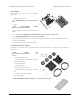
Pololu Zumo Shield for Arduino User’s Guide © 2001–2016 Pololu Corporation Zumo Shield The shield itself comes with the following components: • right-angle slide switch • two pushbuttons [https://www.pololu.com/product/ 1400] • buzzer • 2-pin battery-charging header [https://www.pololu.com/product/1012] • three jumper wires (for soldering motors to the shield) • two 25-pin 0.1″ straight breakaway male headers [https://www.pololu.com/product/965] • four blue shorting blocks [https://www.pololu.
Pololu Zumo Shield for Arduino User’s Guide © 2001–2016 Pololu Corporation You will receive the black acrylic spacer and mounting plates with protective paper masking on both sides. You can peel this masking off to expose the acrylic surface, or you can leave it on to increase the thickness of the plates. The shield and chassis kit include extra parts like jumper wires, screws, nuts, and washers, so do not be concerned if you have some leftover hardware after assembling your Zumo.
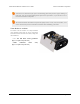
Pololu Zumo Shield for Arduino User’s Guide © 2001–2016 Pololu Corporation 2. Assembly If you have a Zumo robot kit for Arduino [https://www.pololu.com/product/2509] or a separate Zumo Shield [https://www.pololu.com/product/2508] and chassis [https://www.pololu.com/product/1418], this section will guide you through assembling them into a complete robot. If you purchased an assembled Zumo robot for Arduino [https://www.pololu.
Pololu Zumo Shield for Arduino User’s Guide © 2001–2016 Pololu Corporation • Small Phillips screwdriver • 3 mm Allen wrench (hex key) • long-nose pliers (for bending the Zumo blade mounting tabs) 2.b. Assembling the Zumo Shield and chassis Please follow these instructions carefully to assemble your Zumo Shield and chassis properly. (These pictures show the original Zumo Shield [https://www.pololu.com/product/2504], but the assembly process is the same for the latest v1.2 version [https://www.pololu.
Pololu Zumo Shield for Arduino User’s Guide © 2001–2016 Pololu Corporation temperature is not excessively hot and avoid holding the iron on a single pin for more than a few seconds as this could melt the Arduino’s female headers. 4. On the bottom of the board, trim the four Arduino header pins closest to the front of the board on each side to prevent them from contacting the motor housings.
Pololu Zumo Shield for Arduino User’s Guide © 2001–2016 Pololu Corporation Instead of making a wire connection, you can solder a 1×3 male header to the buzzer jumper holes to allow the use of a shorting block for connecting the buzzer. You can also use male headers and shorting blocks for the battery level jumper and compass jumpers if you have an Arduino Uno with an SMD (surface mount) microcontroller, Arduino Leonardo, or A-Star 32U4 Prime.
Pololu Zumo Shield for Arduino User’s Guide © 2001–2016 Pololu Corporation 8. Solder a pair of leads to each motor. You might find it helpful to make a small bend at the tip of each lead to hook into the hole in the motor lead tab to hold it in place for soldering.
Pololu Zumo Shield for Arduino User’s Guide © 2001–2016 Pololu Corporation 9. Place the motors into the channel in the front of the chassis, aligning the gearbox with the grooves in the channel. The front plate of the gearbox should be even with the edge of the chassis. Chassis and shield To assemble the chassis with the Zumo Shield, you should use the two-piece acrylic spacer plate that is included with the shield. You will not need the one-piece mounting plate that is included with the Zumo chassis.
Pololu Zumo Shield for Arduino User’s Guide © 2001–2016 Pololu Corporation different sizes of #2-56 machine screws: 1/4″and 5/16″. The two longer screws are intended for use in the front holes (near the motors) if you are also mounting a sumo blade; otherwise, you can use the shorter 1/4″ screws for all four mounting holes. If you are also adding a basic sumo blade, you can either mount it now or add it later after you are done soldering the motors and battery contacts.
Pololu Zumo Shield for Arduino User’s Guide © 2001–2016 Pololu Corporation Battery contacts 15. Turn the chassis over and install the battery terminal contacts as shown in the picture below. The three double-contact pieces should be firmly pressed into place until they are flush with the interior surface of the battery compartment.
Pololu Zumo Shield for Arduino User’s Guide © 2001–2016 Pololu Corporation 16. Solder the two individual contacts to the shield from the top. Note that if you are using a battery to hold the contact in place during soldering, the battery might act as a heat sink, making it more difficult to solder or requiring a higher soldering iron temperature. The battery terminal slot in the PCB should be completely filled with solder as shown in the picture below. Sprockets and track 17.
Pololu Zumo Shield for Arduino User’s Guide © 2001–2016 Pololu Corporation shoulder bolts as doing so can bend the washers. Note: Be careful if you use threadlocking adhesives like Loctite as these can corrode the chassis. You should first test any such adhesives on a concealed part of the chassis to ensure they will not damage it. 19. Press the output shafts of the motors into the drive sprockets, with the “teeth” of the sprockets facing the motor.
Pololu Zumo Shield for Arduino User’s Guide © 2001–2016 Pololu Corporation Disassembly If you later decide you want to solder additional parts to the Zumo Shield, it is possible to remove it from the chassis with some careful effort. 1. Remove the tracks from the chassis and carefully pull the drive sprockets off the motors. 2. Remove the battery cover and batteries from the chassis. 2.
Pololu Zumo Shield for Arduino User’s Guide © 2001–2016 Pololu Corporation 3. Unscrew all four sets of machine screws and nuts holding the shield to the chassis. 4. Squeeze the negative battery terminal spring and gently ease both battery terminals out through the holes in the chassis. The motors will stay attached to the shield as it separates from the chassis. 5. Carefully bend both motors away from the shield to allow the front piece of the spacer plate to be removed.
Pololu Zumo Shield for Arduino User’s Guide © 2001–2016 Pololu Corporation Assembling the sensor array The Zumo reflectance sensor array ships with all of the components you need to connect it to a Zumo shield: • sensor array PCB with the surface-mount parts pre-populated • 2×12 extended 0.1″ male header (will be soldered to sensor PCB) • 2×12 0.1″ female header (will be soldered to Zumo shield) • 1×3 0.1″ straight male header (optionally soldered to sensor PCB) • 1×3 0.
Pololu Zumo Shield for Arduino User’s Guide © 2001–2016 Pololu Corporation The extended 2×12 male header strip should be mounted to the sensor array PCB on the opposite side from the components.
Pololu Zumo Shield for Arduino User’s Guide © 2001–2016 Pololu Corporation With the female header in place, the assembled sensor array can be plugged directly into the Zumo shield. The reflectance sensor array features two visible (red) LEDs in series with the IR emitter LEDs, so you can use the red LEDs to tell when the emitters are on and off. Array pinout The Zumo reflectance sensor array gets all the necessary power and I/O connections from the 12 header pins that are circled on the silkscreen: 2.
Pololu Zumo Shield for Arduino User’s Guide © 2001–2016 Pololu Corporation The default I/O connections are to pins that are otherwise unused by the Zumo shield. The shield uses one digital I/O pin for each sensor (5, A2, A0, 11, A3, and 4), and if you add the LEDON shorting block, one additional pin (either A4 or 2) is used. To configure the ZumoReflectanceSensorArray library [https://www.pololu.com/docs/ 0J57/6] to use this default pinout, simply call init with no arguments: reflectanceSensors.
Pololu Zumo Shield for Arduino User’s Guide © 2001–2016 Pololu Corporation side of the PCB between the two holes of each pair, and this trace can be cut to disable the sensor and free up the I/O line. The proper place to cut is marked on the silkscreen by carets. For example, if you want to use your Zumo for solving a line maze, you can likely get by with just four sensors: you can use the middle two sensors for tracking the line and the outer two sensors for detecting intersections.
Pololu Zumo Shield for Arduino User’s Guide © 2001–2016 Pololu Corporation To configure the ZumoReflectanceSensorArray library to use this remapped configuration, call init with these arguments: byte pins[] = {4, A5, 11, A0, A2, 5}; reflectanceSensors.init(pins, 6); Or, if you are not using an I/O line to control the IR emitters: byte pins[] = {4, A5, 11, A0, A2, 5}; reflectanceSensors.init(pins, 6, 2000, QTR_NO_EMITTER_PIN); 2.
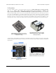
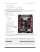
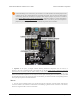
Pololu Zumo Shield for Arduino User’s Guide © 2001–2016 Pololu Corporation 3. The Zumo Shield in detail 3.a. Features and components The main features of the Zumo Shield (v1.2) are labeled in this diagram: For the original Zumo Shield, a corresponding diagram [https://www.pololu.com/file/download/zumo-shield-v1.0-labeledcomponents.jpg?file_id=0J810] (206k jpg) is available (the only differences are the on-board inertial sensors). Power The Zumo chassis has an internal compartment for four AA batteries.
Pololu Zumo Shield for Arduino User’s Guide © 2001–2016 Pololu Corporation After passing through reverse protection, the battery voltage is connected to the rest of the shield by the power switch. The switched battery voltage is designated VBAT and provides power to the motors through the DRV8835 motor driver. An on-board boost regulator, also supplied from VBAT, generates 7.45 V to power the Arduino through its Vin pin. In turn, the Arduino’s regulated 5V and 3.
Pololu Zumo Shield for Arduino User’s Guide © 2001–2016 Pololu Corporation The ZumoMotors library [https://www.pololu.com/docs/0J57/6] provides functions that allow you to easily control the motors, and it can optionally take care of flipping a direction signal for you if you accidentally soldered in a motor backwards.
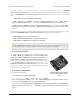
Pololu Zumo Shield for Arduino User’s Guide © 2001–2016 Pololu Corporation This diagram is also available as a downloadable PDF: Zumo Shield front expansion pinout [https://www.pololu.com/file/download/zumo_shield_front_expansion_pinout.pdf?file_id=0J592] (552k pdf). The front expansion makes available digital pins 2, 4, 5, and 11 and analog pins A0 through A5. It also provides access to the two I²C pins (SDA and SCL).
Pololu Zumo Shield for Arduino User’s Guide © 2001–2016 Pololu Corporation • The battery level jumper connects the Arduino’s analog pin 1 to a voltage divider circuit that allows you to monitor the Zumo’s battery voltage. This jumper is disconnected by default and can be connected by soldering a short length of wire between the two holes. The divider outputs a voltage equal to two-thirds of the battery voltage, which will always be safely below the Arduino’s maximum analog input voltage of 5 V.
Pololu Zumo Shield for Arduino User’s Guide © 2001–2016 Pololu Corporation • The compass/gyro I²C jumpers connect the I²C clock (SCL) and data (SDA) lines of the inertial sensors on the Zumo Shield to the SCL and SDA pins on the Arduino. These jumpers are connected by default, but can be disconnected by cutting the thin trace between each pair of holes. On the Arduino Uno R3, SCL and SDA are duplicates of analog pins 5 and 4, respectively.
Pololu Zumo Shield for Arduino User’s Guide © 2001–2016 Pololu Corporation and SDA pins on the Zumo Shield by default, but they can be disconnected by cutting traces to allow those pins to be used for other purposes. It is necessary to make some additional connections on the shield if you want to use the compass with an older Arduino without separate SCL and SDA pins; please see Section 3.c for more details about the compass connections. We have written a basic LSM303 Arduino library [https://github.
Pololu Zumo Shield for Arduino User’s Guide © 2001–2016 Pololu Corporation 4. Schematic diagrams Schematic diagrams of the Zumo Shield are available as a downloadable PDF: • v1.2 v1_2-schematic.pdf?file_id=0J779] Zumo Shield schematic (449k pdf) • Original Shield Zumo zumo_shield_schematic.pdf?file_id=0J591] 4. Schematic diagrams diagrams schematic (121k pdf) [https://www.pololu.com/file/download/zumo-shield- diagrams [https://www.pololu.
Pololu Zumo Shield for Arduino User’s Guide © 2001–2016 Pololu Corporation 5.
Pololu Zumo Shield for Arduino User’s Guide © 2001–2016 Pololu Corporation 6. Zumo Shield Arduino Libraries Our Zumo Shield Libraries make it easy to get started writing Arduino sketches to control your Zumo. A link to download the library and installation instructions can be found on the libraries’ github page [https://github.com/ pololu/zumo-shield].
Pololu Zumo Shield for Arduino User’s Guide © 2001–2016 Pololu Corporation QTRSensors This library, which can also be found in the qtr-sensors-arduino repository [https://github.com/pololu/qtr-sensorsarduino], is a general library for interfacing with Pololu QTR reflectance sensors [https://www.pololu.com/category/ 123/pololu-qtr-reflectance-sensors]. Since the Zumo reflectance sensor array [https://www.pololu.
Pololu Zumo Shield for Arduino User’s Guide © 2001–2016 Pololu Corporation 7. Example projects These examples demonstrate how to program an Arduino-controlled Zumo to perform more complex and interesting tasks. The source files for the examples are included in the download for the Zumo Shield Arduino Libraries [https://www.pololu.com/docs/0J57/6]. Once the libraries are installed, the examples can be accessed in the Arduino environment under File > Examples > ZumoExamples. 7.a.
Pololu Zumo Shield for Arduino User’s Guide © 2001–2016 Pololu Corporation Diagram of an RC receiver connected to pins on a Zumo Shield. This program uses Arduino’s PulseIn library [http://arduino.cc/en/Reference/PulseIn] to read the signals from the receiver. By default, it assumes the throttle and steering channels are connected as the diagram shows on pins 4 and 5, respectively.
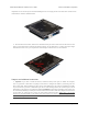
Pololu Zumo Shield for Arduino User’s Guide A Zumo robot preparing to attack a Parallax SumoBot. © 2001–2016 Pololu Corporation Zumo reflectance sensor array on a Zumo robot, bottom view. This example demonstrates how to program an Arduino-controlled Zumo equipped with a reflectance sensor array to drive around and stay within a sumo ring. Note that it only uses the two outermost sensors on the array, which are sufficient for border detection. With the Zumo Shield Arduino Libraries [https://www.pololu.
Pololu Zumo Shield for Arduino User’s Guide © 2001–2016 Pololu Corporation next step, you might consider adding more sensors, such as range finders [https://www.pololu.com/category/79/sharpdistance-sensors], to allow the Zumo to find its opponent instead of relying on luck to make contact. 7.c. Collision-detecting sumo robot This example extends the simple border-detecting sumo robot example [https://www.pololu.com/docs/0J57/7.
Pololu Zumo Shield for Arduino User’s Guide © 2001–2016 Pololu Corporation fields (e.g. from rebar in a concrete floor) from affecting the Zumo’s navigation too much, the program measures the magnetic heading before each turn, then turns ninety degrees relative to that heading. 7.
Pololu Zumo Shield for Arduino User’s Guide © 2001–2016 Pololu Corporation 8. Controlling a servo This section explains how to control a hobby RC servo [https://www.pololu.com/category/23/rc-servos] from an Arduino Uno, Arduino Leonardo, or A-Star 32U4 Prime that is connected to the Zumo Shield. The Arduino IDE includes a Servo [http://arduino.cc/en/Reference/Servo] library that generates the pulses needed to control an RC servo.
Pololu Zumo Shield for Arduino User’s Guide © 2001–2016 Pololu Corporation // The time that passed since the last interrupt is OCR2A + 1 // because the timer value will equal OCR2A before going to 0. servoTime += OCR2A + 1; static uint16_t highTimeCopy = 3000; static uint8_t interruptCount = 0; if(servoHigh) { if(++interruptCount == 2) { OCR2A = 255; } // The servo pin is currently high. // Check to see if is time for a falling edge. // Note: We could == instead of >=.
Pololu Zumo Shield for Arduino User’s Guide © 2001–2016 Pololu Corporation 8.b. Controlling a servo with an Arduino Leonardo or A-Star 32U4 Prime It is possible to modify the Servo library that comes with the Arduino IDE to use Timer 3 instead of Timer 1 on the Arduino Leonardo or A-Star 32U4 Prime. The modified Servo library does not interfere with the ZumoMotors library, making it possible to simultaneously control servos and the motors.