Pololu Zumo Shield for Arduino User’s Guide © 2001–2019 Pololu Corporation Pololu Zumo Shield for Arduino User’s Guide https://www.pololu.
Pololu Zumo Shield for Arduino User’s Guide © 2001–2019 Pololu Corporation 1. Overview . . . . . . . . . . . . . . . . . . . . . . . . . . . . . . . . . . 1.a. Contacting Pololu . . . . . . . . . . . . . . . . . . . . . . . . . . 1.b. Included components . . . . . . . . . . . . . . . . . . . . . . . . 2. Assembly . . . . . . . . . . . . . . . . . . . . . . . . . . . . . . . . . . 2.a. What you will need . . . . . . . . . . . . . . . . . . . . . . . . . 2.b. Assembling the Zumo Shield and chassis . . . . .
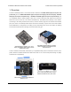
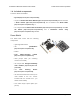
Pololu Zumo Shield for Arduino User’s Guide © 2001–2019 Pololu Corporation 1. Overview The Zumo Shield provides a convenient interface between our Zumo chassis [https://www.pololu.com/ product/1418] and an A-Star 32U4 Prime [https://www.pololu.com/category/165/a-star-32u4-prime], Arduino Uno [https://www.pololu.com/product/2191], or Arduino Leonardo [https://www.pololu.
Pololu Zumo Shield for Arduino User’s Guide © 2001–2019 Pololu Corporation The latest revision of the Zumo Shield is version 1.2. This version adds an L3GD20H [https://www.pololu.com/product/2129] 3-axis gyroscope and upgrades the accelerometer and magnetometer chip to the newer LSM303D [https://www.pololu.com/product/2127]. It is available by itself, as part of a kit, or in a complete robot: • Zumo Shield, v1.2 [https://www.pololu.com/product/2508] • Zumo robot kit for Arduino, v1.2 [https://www.pololu.
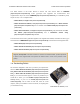
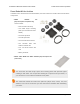
Pololu Zumo Shield for Arduino User’s Guide © 2001–2019 Pololu Corporation 1.b. Included components The Zumo Shield is available: • by itself [https://www.pololu.com/product/2508]; • as part of a Zumo robot kit for Arduino [https://www.pololu.com/product/2509] that also includes a Zumo chassis [https://www.pololu.com/product/1418] [https://www.pololu.com/product/1410]; or • as a fully-assembled Zumo robot for Arduino HP motors [https://www.pololu.com/product/2510] [https://www.pololu.
Pololu Zumo Shield for Arduino User’s Guide © 2001–2019 Pololu Corporation Zumo Robot Kit for Arduino In addition to the shield and its included hardware, the Zumo robot kit for Arduino also includes these components: • Zumo chassis kit [https://www.pololu.
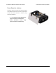
Pololu Zumo Shield for Arduino User’s Guide © 2001–2019 Pololu Corporation Zumo Robot for Arduino The Zumo robot for Arduino is a fully-assembled robot platform built from the same components found in the Zumo robot kit for Arduino, along with these additions: • Two 75:1 HP micro metal gearmotors [https://www.pololu.com/product/2361] • Zumo reflectance sensor array [https://www.pololu.com/product/1419] 1.
Pololu Zumo Shield for Arduino User’s Guide © 2001–2019 Pololu Corporation 2. Assembly If you have a Zumo robot kit for Arduino [https://www.pololu.com/product/2509] or a separate Zumo Shield [https://www.pololu.com/product/2508] and chassis [https://www.pololu.com/product/1418], this section will guide you through assembling them into a complete robot. If you purchased an assembled Zumo robot for Arduino [https://www.pololu.
Pololu Zumo Shield for Arduino User’s Guide © 2001–2019 Pololu Corporation [https://www.pololu.com/category/123/pololu-qtr-reflectance-sensors] • Connectors and jumper wires [https://www.pololu.com/category/19/connectors], for connecting additional sensors and components • Battery charger (such as the iMAX-B6AC [https://www.pololu.
Pololu Zumo Shield for Arduino User’s Guide © 2001–2019 Pololu Corporation Through-hole parts 1. Solder the included through-hole components to the shield: ◦ power switch ◦ reset pushbutton ◦ user pushbutton ◦ buzzer ◦ charging connector (1×2-pin female header) 2. On the bottom of the board, trim any leads longer than 1/16″ (the thickness of the spacer plate) so they do not prevent the shield from sitting flat on the spacer plate and chassis. Arduino headers 3.
Pololu Zumo Shield for Arduino User’s Guide © 2001–2019 Pololu Corporation one 1×10 header, two 1×8 headers, and one 1×6 header; older Arduino boards use two 1×8 headers and two 1×6 headers (the two pairs of pins highlighted above in red should not be populated if you are using this board with an older Arduino that does not support these additional pins).
Pololu Zumo Shield for Arduino User’s Guide © 2001–2019 Pololu Corporation Jumpers and additional connections 5. Optional: If you want to enable the buzzer, enable the battery level input, or disable the compass, now is a good time to add and/or cut jumper connections to configure the shield to your liking.
Pololu Zumo Shield for Arduino User’s Guide © 2001–2019 Pololu Corporation 6. Optional: At this point, you might consider soldering additional components (such as sensors), or headers or wires for connecting them, to the shield. If you do this, please check to make sure your part placement does not interfere with the shield’s ability to mate with the Arduino or the chassis.
Pololu Zumo Shield for Arduino User’s Guide © 2001–2019 Pololu Corporation 8. Cut two of the included jumper wires in half to form four segments, and trim off the ends that are covered in adhesive (the adhesive could interfere with making a good electrical connection to the motor). These wire segments will be used as motor leads. 9. Solder a pair of leads to each motor in the orientation described below.
Pololu Zumo Shield for Arduino User’s Guide © 2001–2019 Pololu Corporation Each motor’s positive terminal is indicated by a plus sign (+) in the black plastic end of the motor, as indicated in the picture below. The motors should be soldered into the shield with the positive terminal closest to the front, so you should attach the leads to allow the motors to be oriented this way. (However, don’t worry if you accidentally get the orientation of one or both motors wrong.
Pololu Zumo Shield for Arduino User’s Guide © 2001–2019 Pololu Corporation Chassis and shield To assemble the chassis with the Zumo Shield, you should use the two-piece acrylic spacer plate that is included with the shield. You will not need the one-piece mounting plate that is included with the Zumo chassis. 11. Place an M3 nut in each of the two side slots near the rear of the chassis. The slots are sized so that nuts will not be able to rotate within them.
Pololu Zumo Shield for Arduino User’s Guide © 2001–2019 Pololu Corporation holes in the spacer plate should line up with the through-holes in the shield resting on top of it, and the motor leads should be aligned so they pass through the slots in the spacer as shown in the picture below. There is only one correct orientation for these plates. (The plate consists of two separate pieces to make it possible to disassemble the Zumo without having to desolder the motors or battery terminals.) 14.
Pololu Zumo Shield for Arduino User’s Guide © 2001–2019 Pololu Corporation mounting a sumo blade; otherwise, you can use the shorter 1/4″ screws for all four mounting holes. If you are also adding a basic sumo blade, you can either mount it now or add it later after you are done soldering the motors and battery contacts.
Pololu Zumo Shield for Arduino User’s Guide © 2001–2019 Pololu Corporation the shield so that the holes line up with the two front mounting holes and insert the two longer (5/16″) #2-56 machine screws (included with the shield) through the blade, shield, spacer plate, and chassis. Be careful when adjusting the angle of the sumo blade while it is mounted to the chassis, as this can crack the acrylic spacer plate if you apply sudden or excessive force.
Pololu Zumo Shield for Arduino User’s Guide © 2001–2019 Pololu Corporation Battery contacts 16. Turn the chassis over and install the battery terminal contacts as shown in the picture below. The three double-contact pieces should be firmly pressed into place until they are flush with the interior surface of the battery compartment.
Pololu Zumo Shield for Arduino User’s Guide © 2001–2019 Pololu Corporation 17. Solder the two individual contacts to the shield from the top. Note that if you are using a battery to hold the contact in place during soldering, the battery might act as a heat sink, making it more difficult to solder or requiring a higher soldering iron temperature. The battery terminal slot in the PCB should be completely filled with solder as shown in the picture below. Idler Sprockets and track 18.
Pololu Zumo Shield for Arduino User’s Guide © 2001–2019 Pololu Corporation 20. At this point, you can add the silicone tracks by stretching them around the sprockets on each side of the chassis. Your Zumo Shield and chassis are now complete; just add batteries and an Arduino to get your Zumo robot moving! 2.
Pololu Zumo Shield for Arduino User’s Guide © 2001–2019 Pololu Corporation Disassembly If you later decide you want to solder additional parts to the Zumo Shield, it is possible to remove it from the chassis with some careful effort. 1. Remove the tracks from the chassis. 2. Remove the battery cover and batteries from the chassis. 3. Unscrew all four sets of machine screws and nuts holding the shield to the chassis. 4.
Pololu Zumo Shield for Arduino User’s Guide © 2001–2019 Pololu Corporation Assembling the sensor array The Zumo reflectance sensor array ships with all of the components you need to connect it to a Zumo shield: • sensor array PCB with the surfacemount parts pre-populated • 2×12 extended 0.1″ male header (will be soldered to sensor PCB) • 2×12 0.1″ female header (will be soldered to Zumo shield) • 1×3 0.1″ straight male header (optionally soldered to sensor PCB) • 1×3 0.
Pololu Zumo Shield for Arduino User’s Guide © 2001–2019 Pololu Corporation We recommend using the right-angle header mounted as shown in the picture below, but the straight 3-pin header will also work if you do not have anything already soldered to the Zumo shield’s front expansion area that would interfere. If you choose to install this header, please make sure you are doing it in a way that will not prevent installation of the sensor array (e.g.
Pololu Zumo Shield for Arduino User’s Guide © 2001–2019 Pololu Corporation With the female header in place, the assembled sensor array can be plugged directly into the Zumo shield. 2.
Pololu Zumo Shield for Arduino User’s Guide © 2001–2019 Pololu Corporation The reflectance sensor array features two visible (red) LEDs in series with the IR emitter LEDs, so you can use the red LEDs to tell when the emitters are on and off. Array pinout The Zumo reflectance sensor array gets all the necessary power and I/O connections from the 12 header pins that are circled on the silkscreen: The default I/O connections are to pins that are otherwise unused by the Zumo shield.
Pololu Zumo Shield for Arduino User’s Guide © 2001–2019 Pololu Corporation Disabling or remapping sensors Many applications do not require all six reflectance sensors, and you might want additional I/O lines for other things (e.g. obstacle detectors). In such cases, you can disable specific sensors and free up their associated I/O lines. The array PCB has six pairs of through holes, each of which corresponds to a different sensor. The order of the pairs matches the order of the sensors.
Pololu Zumo Shield for Arduino User’s Guide © 2001–2019 Pololu Corporation Now you effectively have a four-sensor array and analog pins A2 and A3 are available for generalpurpose use. To configure the ZumoReflectanceSensorArray object to use this new configuration, call init with these arguments: 1 2 ? byte pins[] = {4, 11, A0, 5}; reflectanceSensors.
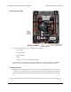
Pololu Zumo Shield for Arduino User’s Guide © 2001–2019 Pololu Corporation 3. The Zumo Shield in detail 3.a. Features and components The main features of the Zumo Shield (v1.2) are labeled in this diagram: For the original Zumo Shield, a corresponding diagram v1.0-labeled-components.jpg] [https://www.pololu.com/file/0J810/zumo-shield- (206k jpg) is available (the only differences are the on-board inertial sensors). Power The Zumo chassis has an internal compartment for four AA batteries.
Pololu Zumo Shield for Arduino User’s Guide © 2001–2019 Pololu Corporation edge of the shield, which can be used to recharge the Zumo’s batteries without removing them from the chassis. The positive pin of the charge connector, on the left, is indicated by a plus sign (+). A charger like the iMAX-B6AC [https://www.pololu.com/product/2588], connected by clipping its alligator clips to a pair of jumper wires inserted into the charge connector, works well for charging the Zumo.
Pololu Zumo Shield for Arduino User’s Guide © 2001–2019 Pololu Corporation the Arduino’s internal pull-up to pull the pin high otherwise. The Pushbutton part of our Zumo Shield Arduino library [https://www.pololu.com/docs/0J57/6], makes it easy to detect and debounce button presses with this pushbutton. Motor driver An integrated DRV8835 [https://www.pololu.com/product/2135] dual motor driver on the Zumo Shield drives the Zumo’s two micro metal gearmotors.
Pololu Zumo Shield for Arduino User’s Guide © 2001–2019 Pololu Corporation • The v1.2 Zumo Shield features an LSM303D 3-axis accelerometer and magnetometer and an L3GD20H 3-axis gyroscope. • The original Zumo Shield features an LSM303DLHC 3-axis accelerometer and magnetometer. The inertial sensors are detailed in Section 3.d. 3.b.
Pololu Zumo Shield for Arduino User’s Guide © 2001–2019 Pololu Corporation pins on the Zumo Shield will not be connected to anything. To use an I²C device on those pins, you can connect SDA to A4 and SCL to A5 yourself by bridging across those two sets of pins in the front expansion area. Section 3.c further explains the I²C lines and the jumpers connecting them to the onboard compass module.
Pololu Zumo Shield for Arduino User’s Guide © 2001–2019 Pololu Corporation • The battery level jumper connects the Arduino’s analog pin 1 to a voltage divider circuit that allows you to monitor the Zumo’s battery voltage. This jumper is disconnected by default and can be connected by soldering a short length of wire between the two holes. The divider outputs a voltage equal to two-thirds of the battery voltage, which will always be safely below the Arduino’s maximum analog input voltage of 5 V.
Pololu Zumo Shield for Arduino User’s Guide © 2001–2019 Pololu Corporation with the label 32U4 to connect the BZ pin to digital pin 6. These are the pins our Zumo Shield Arduino library [https://www.pololu.com/docs/0J57/6] expects the buzzer to be connected to for each respective microcontroller. More details about the buzzer can be found in Section 3.a.
Pololu Zumo Shield for Arduino User’s Guide © 2001–2019 Pololu Corporation All versions of the Zumo Shield have a compass module that combines a 3-axis accelerometer and 3-axis magnetometer into a single package with an I²C interface. This chip is an LSM303D [https://www.pololu.com/product/2127] on the v1.2 shield or an LSM303DLHC [https://www.pololu.com/product/ 2124] on the original Zumo Shield. The v1.2 version of the Zumo Shield also adds an L3GD20H [https://www.pololu.
Pololu Zumo Shield for Arduino User’s Guide © 2001–2019 Pololu Corporation a particular environment, they can be used to help the Zumo turn left or right by a specific angle instead of just timing how long to run the motors to make such a turn. In our tests, we found that the batteries, motors, and motor current affect the z axis of the magnetometer much more strongly than the x and y axes, so you probably will want to ignore the z readings.
Pololu Zumo Shield for Arduino User’s Guide © 2001–2019 Pololu Corporation 4. Schematic diagrams Schematic diagrams of the Zumo Shield are available as a downloadable PDF: • v1.2 Zumo Shield v1_2-schematic.pdf] • Original schematic [https://www.pololu.com/file/0J779/zumo-shield- (449k pdf) Zumo Shield zumo_shield_schematic.pdf] 4. Schematic diagrams diagrams schematic diagrams [https://www.pololu.
Pololu Zumo Shield for Arduino User’s Guide © 2001–2019 Pololu Corporation 5.
Pololu Zumo Shield for Arduino User’s Guide © 2001–2019 Pololu Corporation 6. Zumo Shield Arduino library Our Zumo Shield Arduino library makes it easy to get started writing Arduino sketches to control your Zumo. A link to download the library and installation instructions can be found on the library’s GitHub page [https://github.com/pololu/zumo-shield-arduino-library]. The Zumo Shield Arduino library documentation [https://pololu.github.
Pololu Zumo Shield for Arduino User’s Guide © 2001–2019 Pololu Corporation to generate pulse width modulation at a 20 kHz frequency. (See Section 3 for more details about the motor driver and its connections.) If you accidentally soldered a motor to the Zumo Shield backwards (opposite the orientation indicated in the assembly instructions [https://www.pololu.com/docs/0J57/2.b]), you can simply call and/or directions in your code.
Pololu Zumo Shield for Arduino User’s Guide sensors © 2001–2019 Pololu Corporation [https://www.pololu.com/category/123/pololu-qtr-reflectance-sensors]. sensor array [https://www.pololu.com/product/1419] Since the Zumo reflectance has the same interface as the QTR RC reflectance sensors, the ZumoReflectanceSensorArray library uses QTRSensors to read the sensor array. PololuBuzzer PololuBuzzer [https://github.com/pololu/pololu-buzzer-arduino] enables playing notes and songs on a buzzer.
Pololu Zumo Shield for Arduino User’s Guide © 2001–2019 Pololu Corporation 7. Example sketches These examples demonstrate how to program an Arduino-controlled Zumo to perform more complex and interesting tasks. The source files for the examples are included in the download for the Zumo Shield Arduino Library [https://www.pololu.com/docs/0J57/6]. Once the library is installed, the examples can be accessed in the Arduino environment under File > Examples > ZumoShield. 7.a.
Pololu Zumo Shield for Arduino User’s Guide © 2001–2019 Pololu Corporation Diagram of an RC receiver connected to pins on a Zumo Shield. This program uses Arduino’s PulseIn library [http://arduino.cc/en/Reference/PulseIn] to read the signals from the receiver. By default, it assumes the throttle and steering channels are connected as the diagram shows on pins 4 and 5, respectively.
Pololu Zumo Shield for Arduino User’s Guide A Zumo robot preparing to attack a Parallax SumoBot. © 2001–2019 Pololu Corporation Zumo reflectance sensor array on a Zumo robot, bottom view. This example demonstrates how to program an Arduino-controlled Zumo equipped with a reflectance sensor array to drive around and stay within a sumo ring. Note that it only uses the two outermost sensors on the array, which are sufficient for border detection. With the Zumo Shield Arduino library [https://www.pololu.
Pololu Zumo Shield for Arduino User’s Guide © 2001–2019 Pololu Corporation • If you do not hear any sound from the buzzer, make sure you have the buzzer control jumper [https://www.pololu.com/docs/0J57/3.c] configured correctly for your Arduino. The ability to wander around while staying inside a sumo ring is enough to allow a Zumo to compete as a basic sumo robot, but a more advanced robot might be able to detect its opponent and drive toward it directly.
Pololu Zumo Shield for Arduino User’s Guide [https://www.pololu.com/product/975], © 2001–2019 Pololu Corporation and the concepts and strategies involved are explained in detail in Section 8 of the 3pi robot user’s guide [https://www.pololu.com/docs/0J21]. 7.f. Using the compass This example program demonstrates using the magnetometer in the Zumo Shield’s LSM303 3-axis compass module (described in section Section 3.d) to help the Zumo coordinate ninety-degree turns and drive in squares.
Pololu Zumo Shield for Arduino User’s Guide © 2001–2019 Pololu Corporation 8. Controlling a servo This section explains how to control a hobby RC servo [https://www.pololu.com/category/23/rc-servos] from an Arduino Uno, Arduino Leonardo, or A-Star 32U4 Prime that is connected to the Zumo Shield. The Arduino IDE includes a Servo [http://arduino.cc/en/Reference/Servo] library that generates the pulses needed to control an RC servo.
Pololu Zumo Shield for Arduino User’s Guide 1 2 3 4 5 6 7 8 9 10 11 12 13 14 15 16 17 18 19 20 21 22 23 24 25 26 27 28 29 30 31 32 33 34 35 36 37 38 39 40 41 42 43 44 45 46 47 48 49 50 51 52 53 54 55 56 57 58 59 60 61 62 © 2001–2019 Pololu Corporation /** Arduino Uno Timer 2 Servo Example This example code for the Arduino Uno shows how to use Timer 2 on the ATmega328P to control a single servo. This can be useful for people who cannot use the Arduino IDE's Servo library.
Pololu Zumo Shield for Arduino User’s Guide 63 64 65 66 67 68 69 70 71 72 73 74 75 76 77 78 79 80 81 82 83 84 85 86 87 88 89 90 91 92 93 94 95 96 97 98 99 100 101 102 103 104 105 106 107 108 109 110 111 112 113 114 115 116 117 © 2001–2019 Pololu Corporation // The servo pin is currently high. // Check to see if is time for a falling edge. // Note: We could == instead of >=. if(servoTime >= highTimeCopy) { // The pin has been high enough, so do a falling edge.
Pololu Zumo Shield for Arduino User’s Guide © 2001–2019 Pololu Corporation with ZumoMotors, making it possible to simultaneously control servos and the motors. Warning: The modifications described here will affect any sketch for the Arduino Leonardo or A-Star that uses the Servo library. 1. First, you will need to locate the Arduino IDE’s Servo library, and find the file inside it named ServoTimers.h. For the 1.6.x versions of the IDE, this file can be found in libraries/Servo/src/ avr/ServoTimers.h.