
User Manual

© Semiconductor Components Industries, LLC, 2010
August, 2010 − Rev. 2
1 Publication Order Number:
AND8399/D
AND8399/D
How to Measure Bemf on
the SLA-pin
Prepared by: Tom De Ryck
ON Semiconductor
Abstract
To enable the possibility to build very accurate stall− and
steploss algorithms as also torque adaptive applications,
AMIS−305xx has a Speed and Load Angle (SLA) pin which
outputs a voltage that reflects the Bemf (Back Electro
Magnetic Force) voltage of the motor.
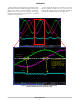
To prevent incorrect use of the SLA−pin, this application
note describes how the motor driver should be operated to
measure the correct Bemf voltage on the SLA−pin.
Introduction
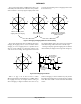
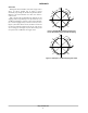
The Bemf is sampled every so called “coil current zero
crossing”. Per coil 2 zero−crossing positions exist per
electrical period, resulting in a total of 4 zero crossings per
electrical period. Or in short, the Bemf voltage can be
measured 4 times per electrical period. Although the Bemf
voltage can
be measured 4 times per electrical period, it does
not mean that it will
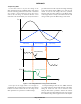
be measured 4 times. The Bemf voltage
will only be sampled by the motor driver if a microstep
position is located on the “coil current zero crossing”. Only
then a correct representation (Note 1) of the Bemf voltage
can be measured on the SLA−pin. If no microstep position
is located on the “coil current zero crossing”, an incorrect
value will be measured on the SLA−pin.
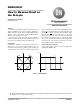
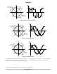
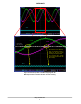
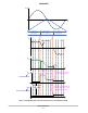
Coil Current Zero Crossings
Next figures display 4 of the in total 7 stepping modes
possible with AMIS−305xx.
Start
t
Figure 1. Full Step Mode
I
Y
I
X
Start
I
coil
I
X
I
Y
1. The voltage measured on the SLA−pin only represents the Bemf voltage. Depending on the SLA Gain setting (see Ref 1) the SLA voltage
will be equal to 1/2 or 1/4 of the real Bemf voltage.
http://onsemi.com
APPLICATION NOTE