
User Manual

AND8399/D
http://onsemi.com
3
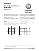
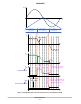
The several stepping modes of AMIS−305xx offers a lot
of flexibility but at the same time could also cause problems
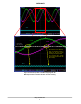
when not used in a correct way. Figure 5 displays what could
go wrong when switching between stepping modes is done
in an incorrect way.
Motor is in full step position,
stepping mode is 1/8 stepping
NXT−pulse is applied.
1/8 of a full step is set.
Stepping mode is changed to
half stepping and several NXT−
pulses are applied
Figure 5. Changing of Stepping Mode in an Incorrect Way
I
X
I
Y
I
Y
I
X
I
Y
I
X
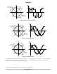
Above figure demonstrates that care should be taken when
changing the stepping mode to a lower resolution. When
changing to a lower stepping mode, it is possible that an
offset is created resulting in no microstep position at the
“coil current zero crossing”. The stepper motor driver will
not sample the Bemf voltage and an incorrect representation
of the Bemf voltage will be measured on the SLA−pin.
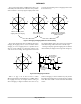
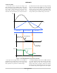
Next figure displays again half stepping but now with the
offset included (as displayed on the right side of Figure 5).
No microstep at
the zero current
crossing!
No microstep at
the zero current
crossing!
t
Figure 6. Half Stepping with Offset
I
Y
I
X
I
Y
I
X
I
coil
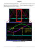
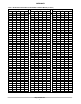
Table 1 on page 7 can be used to know at which
Microstep Position (see Status Register 3 of AMIS−305xx)
the stepping mode may be changed without creating an
offset. Changing to a higher resolution can be done at any
moment. Changing to a lower resolution may only be done
if the Microstep Position is also present in the lower stepping
mode. More info on Table 1 can be found in the SLA Check
section.