Pololu P-Star 25K50 Micro User’s Guide © 2001–2017 Pololu Corporation Pololu P-Star 25K50 Micro User’s Guide View document on multiple pages. [https://www.pololu.com/docs/0J62] You can also view this document as a printable PDF [https://www.pololu.com/docs/pdf/0J62/p-star_25k50.pdf]. https://www.pololu.
Pololu P-Star 25K50 Micro User’s Guide 1. Overview . . . . . . . . . . . . . . . . . . . . . . . . 1.1. Supported operating systems . . . . . . . . . . 2. Contacting Pololu . . . . . . . . . . . . . . . . . . . 3. Pinout and components . . . . . . . . . . . . . . . . 4. Schematic and dimensions . . . . . . . . . . . . . . . 5. Getting started . . . . . . . . . . . . . . . . . . . . . 5.1. Installing p-load and drivers . . . . . . . . . . 5.2. Getting into bootloader mode . . . . . . . . . 5.3.
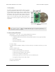
Pololu P-Star 25K50 Micro User’s Guide © 2001–2017 Pololu Corporation 1. Overview The Pololu P-Star 25K50 microcontroller board is a generalpurpose programmable module based on the PIC18F25K50 microcontroller from Microchip, which has 32 KB of flash program memory, 2 KB of RAM and built-in full-speed USB functionality. The P-Star 25K50 adds onboard components and connectors that support the microcontroller and make it easier to use.
Pololu P-Star 25K50 Micro User’s Guide © 2001–2017 Pololu Corporation • Can be powered from USB or external source regulated to 5 V by onboard regulator • Operating voltage: 5.5 V to 15 V ◦ Can operate down to 3.
Pololu P-Star 25K50 Micro User’s Guide © 2001–2017 Pololu Corporation 2. Contacting Pololu We would be delighted to hear from you about any of your projects and about your experience with the Pololu P-Star 25K50 Micro. You can contact us [https://www.pololu.com/contact] directly or post on our forum [http://forum.pololu.com/]. Tell us what we did well, what we could improve, what you would like to see in the future, or anything else you would like to say! 2.
Pololu P-Star 25K50 Micro User’s Guide © 2001–2017 Pololu Corporation 3. Pinout and components P-Star 25K50 Micro pinout diagram. This diagram identifies the I/O and power pins on the P-Star 25K50 Micro. The diagram is also available as a printable PDF [https://www.pololu.com/file/download/p-star-25K50-micro-pinout.pdf?file_id=0J799] (161k pdf). For more information about the PIC18F25K50 microcontroller and its peripherals, see Microchip’s PIC18F25K50 documentation [http://www.microchip.
Pololu P-Star 25K50 Micro User’s Guide © 2001–2017 Pololu Corporation program the board over USB. The USB connection can also provide power to the P-Star. The board also has five pins arranged so that they can be directly plugged into a standard In-Circuit Serial Programming (ICSP) connector, such as the one found on the PICkit 3. More information about programming with the PICkit 3 can be found in Section 7. The five pins are: MCLR, VDD, GND, RB7, and RB6. The MCLR pin is pin 1.
Pololu P-Star 25K50 Micro User’s Guide © 2001–2017 Pololu Corporation P-Star 25K50 Micro, bottom view. USB power sensing The VB pin, located on the interior of the board, is connected to the USB 5 V bus voltage through a 1 kΩ resistor. By default, the VB pin is also connected to the RA0 pin through a cuttable trace on the bottom of the board between the two pins. This means that RA0 can be used as a digital or analog input to detect the presence of USB power.
Pololu P-Star 25K50 Micro User’s Guide P-Star 25K50 Micro with included optional headers. 3. Pinout and components © 2001–2017 Pololu Corporation The P-Star 25K50 Micro with soldered headers and connected USB cable.
Pololu P-Star 25K50 Micro User’s Guide © 2001–2017 Pololu Corporation 4. Schematic and dimensions Schematic diagram 4.
Pololu P-Star 25K50 Micro User’s Guide © 2001–2017 Pololu Corporation P-Star 25K50 Micro schematic diagram. This schematic is also available as a PDF: P-Star 25K50 Micro schematic diagram [https://www.pololu.com/file/ 4.
Pololu P-Star 25K50 Micro User’s Guide download/p-star-25K50-micro-schematic.pdf?file_id=0J797] © 2001–2017 Pololu Corporation (414k pdf). Dimension diagram A dimension diagram is available as a PDF: P-Star 25K50 Micro dimension diagram [https://www.pololu.com/file/ download/p-star-25K50-micro-dimensions.pdf?file_id=0J798] (202k pdf) 4.
Pololu P-Star 25K50 Micro User’s Guide © 2001–2017 Pololu Corporation 5. Getting started 5.1. Installing p-load and drivers To use the P-Star 25K50 Micro’s USB bootloader, you will need to install a command-line utility called the Pololu USB Bootloader Utility. This program is also known as “p-load” because that is the command used to run it from a command prompt.
Pololu P-Star 25K50 Micro User’s Guide © 2001–2017 Pololu Corporation Another option is to connect a bootloader button between VDD and RB6 and a reset button between GND and MCLR as shown in the picture below, and reset the P-Star while you are holding down the bootloader button. The buttons shown in the picture below are Pololu item #1400 [https://www.pololu.com/product/1400]. P-Star 25K50 Micro on a breadboard with a reset button (left) and a bootloader button (onboard).
Pololu P-Star 25K50 Micro User’s Guide © 2001–2017 Pololu Corporation with a USB virtual COM port could listen for a special baud rate to be set by the computer (we used 333 Baud on the Wixel). 5.3. Compiling a program with MPLAB X and XC8 The P-Star can be programmed using standard development tools from Microchip. This section explains how to get started programming the P-Star in the C language using MPLAB X and XC8. MPLAB X [http://www.microchip.
Pololu P-Star 25K50 Micro User’s Guide © 2001–2017 Pololu Corporation 6. On the “Select Tool” screen, you can select “PICkit 3” but this choice does not matter because we will not use MPLAB X to the load the program onto the board. 7. For the compiler, select XC8. 8. For the Project Name, choose something like “p-star1”, and choose the folder you want it to be in. Click “Finish” to create the project. 5.
Pololu P-Star 25K50 Micro User’s Guide © 2001–2017 Pololu Corporation 9. We need to configure the project’s linker setting to properly account for the P-Star’s bootloader, which takes up the first 8 KB of flash memory. In the “File” menu, select “Project Properties”. In the “XC8 linker” category, select the “Additional options” sub-category. In the “Codeoffset” box enter 0x2000, which is 8*1024 in hex. Click “OK.” 5.
Pololu P-Star 25K50 Micro User’s Guide © 2001–2017 Pololu Corporation 10. Now we need to create the C source file. Locate the “Projects” pane. If the “Projects” pane is not visible, you can open it by opening the “Window” menu and selecting “Projects”. Left-click the “+” sign next to “Source Files” to expand it and verify that your project has no source files yet. Then rightclick on “Source Files”, select “New”, and then select “C Source File…”. 11. Choose a file name like “main” and then click Finish.
Pololu P-Star 25K50 Micro User’s Guide © 2001–2017 Pololu Corporation LATC6 = 0; /* Enable Timer 0 as a 16-bit timer with 1:256 prescaler: since the instruction speed is 12 MHz, this overflows about every 1.4 seconds. */ T0CON = 0b10000111; while(1) { TMR0L; // trigger an update of TMR0H // Blink the green LED with a period of 1.4 s LED_GREEN(TMR0H >> 7 & 1); // Blink the yellow LED with a period of 0.7 s LED_YELLOW(TMR0H >> 6 & 1); } } // Blink the red LED with a period of 0.
Pololu P-Star 25K50 Micro User’s Guide © 2001–2017 Pololu Corporation where HEXFILE is the full or relative path to the HEX file you compiled. When you run this command, the output should look something like: Bootloader: Pololu P-Star 25K50 Bootloader Serial number: 00108214 Erasing flash... Progress: |##########################################################| Done. Writing flash... Progress: |##########################################################| Done. Erasing EEPROM...
Pololu P-Star 25K50 Micro User’s Guide © 2001–2017 Pololu Corporation 6. The P-Star 25K50 Bootloader The P-Star comes with a proprietary bootloader developed by Pololu that uses a native USB protocol. The bootloader allows you to read and write the flash and EEPROM memories of the chip without using an external programmer. 6.1. Memory organization Flash memory sections The bootloader occupies the first 8 KB (8192 bytes) of the PIC microcontroller’s flash memory.
Pololu P-Star 25K50 Micro User’s Guide © 2001–2017 Pololu Corporation Serial number The bootloader comes with a unique serial number that is assigned during manufacturing. This serial number is typically an 8-digit decimal number, but in the future we might expand it to have other characters or make it be up to 16 characters long. The serial number is accessible from the application, and applications using USB can expose the serial number as a string descriptor.
Pololu P-Star 25K50 Micro User’s Guide © 2001–2017 Pololu Corporation The startup logic for the P-Star USB bootloader. 6.3. Bootloader I/O pin usage The bootloader uses the following I/O pins of the microcontroller: • D- and D+ are used to communicate with the USB host. • RB6 is driven high to turn on the yellow LED, but never driven low. • RB7 is driven high to turn on the green LED, but never driven low.
Pololu P-Star 25K50 Micro User’s Guide © 2001–2017 Pololu Corporation USB Configured state. If the device has not reached the Configured state, the green LED will blink on and off with a 50% duty cycle and a period of about 1.4 seconds. If the device has reached the Configured state, then it will do a double-blink every 1.4 seconds. The yellow LED is usually on solid, but it will blink quickly whenever a USB command is received.
Pololu P-Star 25K50 Micro User’s Guide © 2001–2017 Pololu Corporation The SDOMX bit is set to 1, so the SDO (SPI data output) pin is assigned to RB3. The T3CMX bit is set to 1, so the T3CKI (Timer3 clock input) pin is assigned to RC0. The CCP2MX bit is set to 1, so the CCP2 input/output pin is assigned to RC1. Clock selection The P-Star is configured to automatically use the onboard 16 MHz crystal, which is also known as the primary oscillator.
Pololu P-Star 25K50 Micro User’s Guide © 2001–2017 Pololu Corporation 7. Programming using the PICkit 3 Warning: Using a PICkit to program the P-Star will permanently erase its USB bootloader, so you will not be able to program it over USB using the Pololu USB Bootloader Utility. It will also erase the serial number of the device. The PICkit 3 [http://www.microchip.com/pickit3] from Microchip is a hardware debugger and programmer for PIC microcontrollers that can be used to program the P-Star.
Pololu P-Star 25K50 Micro User’s Guide © 2001–2017 Pololu Corporation The P-Star 25K50 Micro connected to a PICkit 3 programmer and a reset button. Another option for connecting a P-Star 25K50 Micro to a PICkit is to solder upwards-pointing header pins on all five programming pins, as shown below. The PICkit 3 can then be directly connected to this five-pin header, or it could be connected through a set of male-female premium jumper wires [https://www.pololu.
Pololu P-Star 25K50 Micro User’s Guide © 2001–2017 Pololu Corporation The P-Star 25K50 Micro with a vertical 5-pin programming header installed. 7.
Pololu P-Star 25K50 Micro User’s Guide © 2001–2017 Pololu Corporation 8. Compiling a USB application with M-Stack This section explains how to compile a USB application using M-Stack [http://www.signal11.us/oss/m-stack/], a USB device stack developed by Signal 11 Software [http://www.signal11.us/]. On the PIC18F25K50, the hardware USB module only implements the lowest levels of the USB protocol, and many other parts of the protocol need to be implemented in firmware.
Pololu P-Star 25K50 Micro User’s Guide © 2001–2017 Pololu Corporation For information about USB, see the USB 2.0 Specification [http://www.usb.org/developers/docs/usb20_docs/]. For information about the USB module on the PIC18F25K50, see the PIC18F25K50 datasheet [http://www.microchip.com/PIC18F25K50]. To write PC software to communicate with the P-Star over USB using a generic USB interface, see libusb [http://libusb.info/]. 8.
Pololu P-Star 25K50 Micro User’s Guide © 2001–2017 Pololu Corporation 9. Compiling a program with MPLAB X and MPASM This section explains how to get started programming the P-Star in assembly using MPLAB X and XC8. MPLAB X [http://www.microchip.com/mplabx] a free integrated development (IDE) from Microchip for programming their PIC microcontrollers. MPASM is an assembler that comes with MPLAB X. For most people, we recommend developing P-Star apps with XC8 [https://www.pololu.com/docs/ 0J62/5.
Pololu P-Star 25K50 Micro User’s Guide © 2001–2017 Pololu Corporation 6. On the “Select Tool” screen, you can select “PICkit 3” but this choice does not matter because we will not use MPLAB X to the load the program onto the board. 7. For the compiler, select MPASM. 8. For the Project Name, choose something like “p-star1”, and choose the folder you want it to be in. Click “Finish” to create the project. 9.
Pololu P-Star 25K50 Micro User’s Guide © 2001–2017 Pololu Corporation 9. In the “File” menu, select “Project Properties”. In the “MPASM (global options)” category, check the “Build in absolute mode” check box, then click “OK”. 10. Now we need to create the assembly source file. Locate the “Projects” pane. If the “Projects” pane is not visible, you can open it by opening the “Window” menu and selecting “Projects”. Left-click 9.
Pololu P-Star 25K50 Micro User’s Guide © 2001–2017 Pololu Corporation the “+” sign next to “Source Files” to expand it and verify that your project has no source files yet. Then right-click on “Source Files”, select “New”, and then select “pic_8b_simple.asm…”. If “pic_8b_simple.asm” is not visible in the menu, you can find it by selecting “Other…”, “Microchip Embedded”, and then “MPASM assembler”. 11. Choose a file name such as “main” and then click “Finish”. This should create a new file named “main.
Pololu P-Star 25K50 Micro User’s Guide bcf return TRISC, 6 ledRedOff: bsf return TRISC, 6 start: bcf LATC, 6 © 2001–2017 Pololu Corporation ; Set up the red LED ; Enable Timer 0 as a 16-bit timer with 1:256 prescaler: ; since the instruction speed is 12 MHz, this overflows about ; every 1.4 seconds. movlw b'10000111' movwf T0CON mainLoop: movf TMR0L, W ; Trigger an update of TMR0H ; Blink btfss rcall btfsc rcall the red LED with a period of 1.4 s.
Pololu P-Star 25K50 Micro User’s Guide © 2001–2017 Pololu Corporation 10. Compiling a program with PICBASIC PRO The P-Star is compatible with PICBASIC PRO, a BASIC language compiler from microEngineering Labs that runs on Microsoft Windows and targets PIC microcontrollers. This section explains how to compile a program and load it onto the P-Star using MicroCode Studio, the IDE that comes with PICBASIC PRO.
Pololu P-Star 25K50 Micro User’s Guide © 2001–2017 Pololu Corporation 6. Click the “Compile” button to compile the program. If you have not saved yet, you will be prompted to choose a location to save the program. After the compilation succeeds, you will have a valid HEX file and you could load it onto the P-Star using the Pololu USB Bootloader Utility (p-load) from the command line.
Pololu P-Star 25K50 Micro User’s Guide © 2001–2017 Pololu Corporation Related products P-Star 25K50 Micro 10.