
Data Sheet


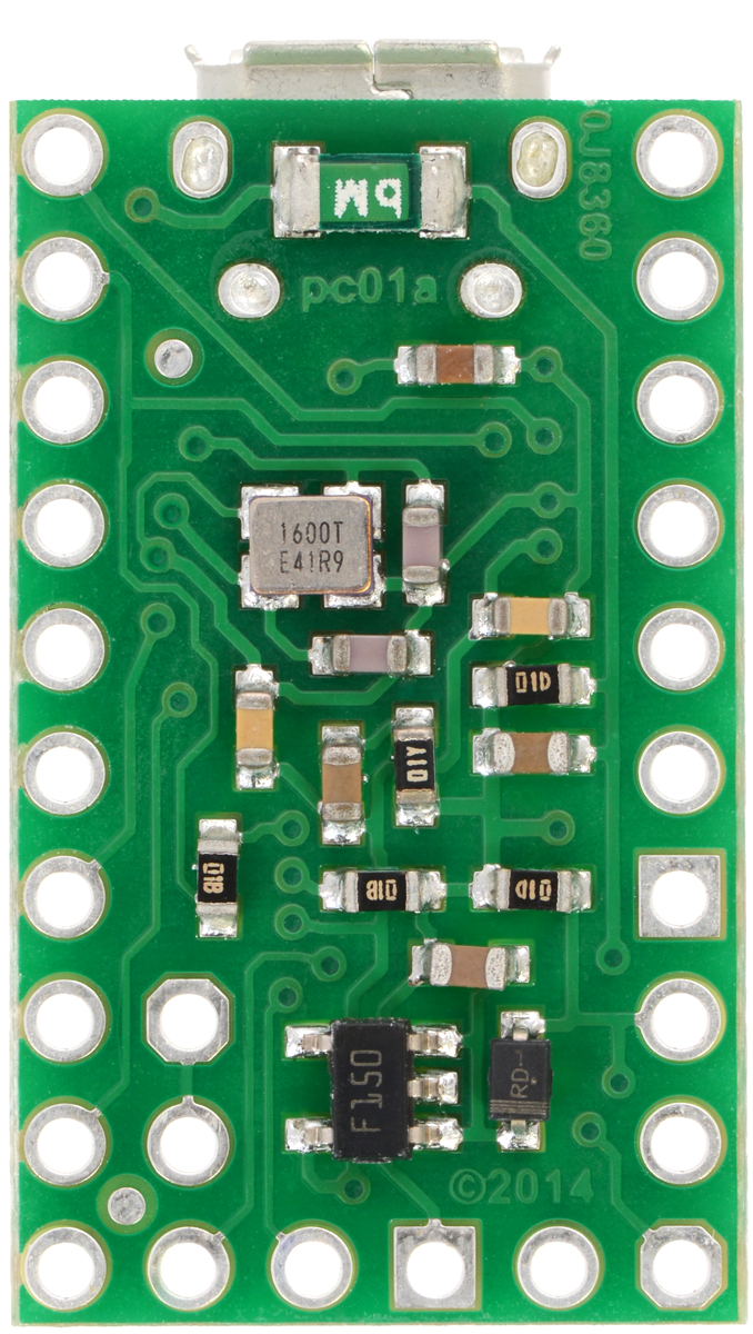
P-Star 25K50 Micro, bottom
view.
USB power sensing
The VB pin, located on the interior of the board, is connected to the USB 5 V bus voltage through a 1 kΩ resistor.
By default, the VB pin is also connected to the RA0 pin through a cuttable trace on the bottom of the board
between the two pins. This means that RA0 can be used as a digital or analog input to detect the presence of
USB power. Cutting the trace between the VB and RA0 pins allows RA0 to be used for other purposes.
Crystal
The P-Star 25K50 Micro has a precision 16 MHz crystal. By default, this crystal is used to provide a clock signal
for the microcontroller and its peripherals.
Included hardware
Two 1×10-pin breakaway 0.1″ male headers [https://www.pololu.com/product/965] and one 1×6-pin breakaway 0.1″
male header are included with the P-Star 25K50 Micro. These header pins can be soldered in to use the board
with perfboards, breadboards [https://www.pololu.com/category/28/solderless-breadboards], or 0.1″ female connectors
[https://www.pololu.com/category/50/0.1-2.54-mm-female-headers].
Pololu P-Star 25K50 Micro User’s Guide © 2001–2017 Pololu Corporation
3. Pinout and components Page 8 of 38