Pololu 3pi Robot User's Guide © 2001–2014 Pololu Corporation Pololu 3pi Robot User's Guide http://www.pololu.
Pololu 3pi Robot User's Guide 1. Introduction . . . . . . . . . . . . . . . . . . . . . . . 2. Contacting Pololu . . . . . . . . . . . . . . . . . . . . 3. Important Safety Warning and Handling Precautions . 4. Getting Started with Your 3pi Robot . . . . . . . . . . 4.a. What You Will Need . . . . . . . . . . . . . . 4.b. Powering Up Your 3pi . . . . . . . . . . . . . 4.c. Using the Preloaded Demo Program . . . . . . 4.d. Included Accessories . . . . . . . . . . . . . . 5. How Your 3pi Works . . . . . . . .
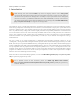
Pololu 3pi Robot User's Guide © 2001–2014 Pololu Corporation 1. Introduction Note: Starting with serial number 0J5840, 3pi robots are shipping with the newer ATmega328P microcontroller instead of the ATmega168. The serial number is located on a white bar code sticker on the bottom of the 3pi PCB.
Pololu 3pi Robot User's Guide © 2001–2014 Pololu Corporation 2. Contacting Pololu You can check the 3pi product page [http://www.pololu.com/product/975] for additional information, including pictures, videos, example code, and other resources. We would be delighted to hear from you about any of your projects and about your experience with the 3pi robot. You can contact us [http://www.pololu.com/contact] directly or post on our forum [http://forum.pololu.com/].
Pololu 3pi Robot User's Guide © 2001–2014 Pololu Corporation 3. Important Safety Warning and Handling Precautions The 3pi robot is not intended for young children! Younger users should use this product only under adult supervision. By using this product, you agree not to hold Pololu liable for any injury or damage related to the use or to the performance of this product.
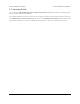
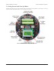
Pololu 3pi Robot User's Guide © 2001–2014 Pololu Corporation 4. Getting Started with Your 3pi Robot Getting started with your 3pi can be as simple as taking it out of the box, adding batteries, and turning it on. The 3pi ships with a demo program that will give you a brief tour of its features. General features of the Pololu 3pi robot, top view. 4.
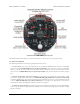
Pololu 3pi Robot User's Guide © 2001–2014 Pololu Corporation Labeled bottom view of the Pololu 3pi robot. The following subsections will give you all the information you need to get your 3pi up and running! 4.a. What You Will Need The following materials are necessary for getting started with your 3pi: • 4 AAA batteries. Any AAA cells will work, but we recommend NiMH batteries, which are rechargeable and can be purchased from Pololu [http://www.pololu.com/product/1002] or at a local store.
Pololu 3pi Robot User's Guide © 2001–2014 Pololu Corporation You might find the following materials useful in creating an environment for your robot to explore: • Several large sheets of white posterboard (available at crafts or office supply stores) or dry-erase whiteboard stock (commonly available at home/construction supply stores). • Light-colored masking tape for joining multiple sheets together. • 3/4" black electrical tape to create lines for your robot to follow. 4.b.
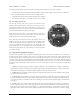
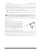
Pololu 3pi Robot User's Guide © 2001–2014 Pololu Corporation all of the sensors should return entirely black readings with IR off. Removing the jumper marked PC5 disables control of the emitters, causing them to always be on. 5. Motors: Hold down A or C to run the motor on the corresponding side, or hold down both buttons to run both motors simultaneously. The motors will gradually ramp up to speed; in your own programs, you can switch them on much more suddenly.
Pololu 3pi Robot User's Guide © 2001–2014 Pololu Corporation 5. How Your 3pi Works 5.a. Batteries Introduction to Batteries The power system on the 3pi begins with the batteries, so it is important to understand how your batteries work. A battery contains a carefully controlled chemical reaction that pulls electrons in from the positive (+) terminal and pushes them out of the negative (-) terminal.
Pololu 3pi Robot User's Guide © 2001–2014 Pololu Corporation output is multiplied by the number of batteries. When they are connected in series, with the positive terminal of one connected to the negative terminal of the next, the maximum current stays the same while the voltage multiplies. Either way, the maximum power output will be multiplied by the number of batteries. Think about two people using two buckets to lift water from a lake to higher ground.
Pololu 3pi Robot User's Guide © 2001–2014 Pololu Corporation • Linear regulators use a simple feedback circuit to vary how much energy is passed through and how much is discarded. The regulator produces a lower output voltage by dumping unneeded energy. This wasteful, inefficient approach makes linear regulators poor choices for applications that have a large difference between the input and output voltages, or for applications that require a lot of current.
Pololu 3pi Robot User's Guide © 2001–2014 Pololu Corporation One other interesting thing about this power system is that instead of gradually running out of power like most robots, the 3pi will operate at maximum performance until it suddenly shuts off. This can take you by surprise, so you might want your 3pi to monitor its battery voltage. A simple circuit for monitoring battery voltage is built in to the 3pi.
Pololu 3pi Robot User's Guide © 2001–2014 Pololu Corporation Motor operation: current and speed vs. torque. The free-running speed of a small DC motor is usually many thousands of rotations per minute (rpm), much higher than the speed we want the wheels of a robot to turn. A gearbox is a system of gears that converts the high-speed, low-torque output of the motor into a lower-speed, higher-torque output that is a much better suited for driving a robot.
Pololu 3pi Robot User's Guide © 2001–2014 Pololu Corporation If switches 1 and 4 are closed (the center picture), current flows through the motor from left to right, and the motor spins forward. Closing switches 2 and 3 causes the current to reverse direction and the motor to spin backward. An H-bridge can be constructed with mechanical switches, but most robots, including the 3pi, use transistors to switch the current electronically.
Pololu 3pi Robot User's Guide Speed control is achieved by rapidly switching the motor between two states in the table. Suppose we keep PD6 high (at 5 V, also called a logical “1”) and have PD5 alternate quickly between low (0 V or “0”) and high. The motor driver will switch between the “forward” and “brake” states, causing M1 to turn forward at a reduced speed. For example, if PD6 is high two thirds of the time (a 67% duty cycle), then M1 will turn at approximately 67% of its full speed.
Pololu 3pi Robot User's Guide © 2001–2014 Pololu Corporation The 3pi demonstrating the effects of various motor settings. 5.d. Digital inputs and sensors The microcontroller at the heart of the 3pi, an Atmel AVR mega168 or mega328, has a number of pins which can be configured as digital inputs: they are read by your program as a 1 or a 0 depending on whether the voltage is high (above about 3 V) or low (below about 1.5 V).
Pololu 3pi Robot User's Guide © 2001–2014 Pololu Corporation The sensing element of the reflectance sensor is the phototransistor shown in the left half of U4, which is connected in series with capacitor C21. A separate connection leads through resistor R12 to pin PC0. This circuit takes advantage of the fact the digital inputs of the AVR can be reconfigured as digital outputs on the fly. A digital output presents a voltage of 5 V or 0 V, depending on whether it is set to a 1 or a 0 by your program.
Pololu 3pi Robot User's Guide © 2001–2014 Pololu Corporation time = 0; last_time = TCNT2; while (time < _maxValue) { // Keep track of the total time. // This implicity casts the difference to unsigned char, so // we don't add negative values.
Pololu 3pi Robot User's Guide © 2001–2014 Pololu Corporation You can download a pdf version of the schematic here [http://www.pololu.com/file/download/3pi-schematic.pdf?file_id=0J119] (481k pdf). 5.
Pololu 3pi Robot User's Guide © 2001–2014 Pololu Corporation 6. Programming Your 3pi To do more with your 3pi than explore the demo program or use it as a serial slave to a master device, you will need to program it, which requires a computer and an external AVR ISP programmer like our USB AVR programmer [http://www.pololu.com/product/1300]. Please see the Pololu AVR Programming Quick Start Guide [http://www.pololu.
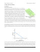
Pololu 3pi Robot User's Guide © 2001–2014 Pololu Corporation 7. Example Project #1: Line Following 7.a. About Line Following Now that you have learned how to compile a simple program for the 3pi, it’s time to teach your robot do something more complicated. In this example project, we’ll show you how to make your 3pi follow a black line on a white background, by coordinating its sensors and motors.
Pololu 3pi Robot User's Guide © 2001–2014 Pololu Corporation function used later in the code also depends on having calibrated values. For more information, see Section 19 of the command reference [http://www.pololu.com/docs/0J18]. 4. Displaying the calibrated line sensor values in a bar graph. This demonstrates the use of the lcd_load_custom_character() function together with print_character() to make it easy to see whether the line sensors are working properly before starting the robot.
Pololu 3pi Robot User's Guide © 2001–2014 Pololu Corporation • Display sensor readings on the LCD. Since writing to the LCD takes a significant amount of time, you should do this at most few times per second. • Incorporate the buzzer into your program. You might want your 3pi to play music while it is driving or make informational beeps that depend on what it is doing. See Section 3 of the command reference [http://www.pololu.
Pololu 3pi Robot User's Guide } © 2001–2014 Pololu Corporation lcd_load_custom_character(levels+4,4); lcd_load_custom_character(levels+5,5); lcd_load_custom_character(levels+6,6); clear(); // the LCD must be cleared for the characters to take effect // This function displays the sensor readings using a bar graph. void display_readings(const unsigned int *calibrated_values) { unsigned char i; for(i=0;i<5;i++) { // Initialize the array of characters that we will use for the // graph.
Pololu 3pi Robot User's Guide © 2001–2014 Pololu Corporation if(counter < 20 || counter >= 60) set_motors(40,-40); else set_motors(-40,40); // This function records a set of sensor readings and keeps // track of the minimum and maximum values encountered. The // IR_EMITTERS_ON argument means that the IR LEDs will be // turned on during the reading, which is usually what you // want. calibrate_line_sensors(IR_EMITTERS_ON); // Since our counter runs to 80, the total delay will be // 80*20 = 1600 ms.
Pololu 3pi Robot User's Guide } } // // // // // // // © 2001–2014 Pololu Corporation right_led(0); } else if(position < 3000) { // We are somewhat close to being centered on the line: // drive straight. set_motors(100,100); left_led(1); right_led(1); } else { // We are far to the left of the line: turn right. set_motors(100,0); left_led(0); right_led(1); } This part of the code is never reached.
Pololu 3pi Robot User's Guide © 2001–2014 Pololu Corporation // Compute the derivative (change) and integral (sum) of the // position. int derivative = proportional - last_proportional; integral += proportional; // Remember the last position. last_proportional = proportional; Note that we cast the variable position to an int type in the formula for proportional. An unsigned int can only store positive values, so the expression position-2000, without casting, would lead to a negative overflow.
Pololu 3pi Robot User's Guide © 2001–2014 Pololu Corporation 8. Example Project #2: Maze Solving 8.a. Solving a Line Maze The next step up from simple line following is to teach your 3pi to navigate paths with sharp turns, dead ends, and intersections. Make a complicated network of intersecting black lines, add a circle to represent the goal, and you have a line maze, which is a challenging environment for a robot to explore.
Pololu 3pi Robot User's Guide } © 2001–2014 Pololu Corporation switch(dir) { case 'L': // Turn left. set_motors(-80,80); delay_ms(200); break; case 'R': // Turn right. set_motors(80,-80); delay_ms(200); break; case 'B': // Turn around. set_motors(80,-80); delay_ms(400); break; case 'S': // Don't do anything! break; } The first line of the file, like any C file that you will be writing for the 3pi, contains an include command that gives you access to the functions in the Pololu AVR Library.
Pololu 3pi Robot User's Guide © 2001–2014 Pololu Corporation // The "proportional" term should be 0 when we are on the line. int proportional = ((int)position) - 2000; // Compute the derivative (change) and integral (sum) of the // position. int derivative = proportional - last_proportional; integral += proportional; // Remember the last position. last_proportional = proportional; // Compute the difference between the two motor power settings, // m1 - m2.
Pololu 3pi Robot User's Guide © 2001–2014 Pololu Corporation that on the way, since you’ll travel down every hallway exactly twice. We use this simple, reliable strategy in our 3pi maze solving example: // This function decides which way to turn during the learning phase of // maze solving. It uses the variables found_left, found_straight, and // found_right, which indicate whether there is an exit in each of the // three directions, applying the "left hand on the wall" strategy.
Pololu 3pi Robot User's Guide } © 2001–2014 Pololu Corporation } The first main loop needs to drive down a segment of the course, decide how to turn, and record the turn in the path variable. To pass the correct arguments to select_turn(), we need to carefully examine the intersection as we cross it. Note that there is a special exception for finding the end of the maze.
Pololu 3pi Robot User's Guide © 2001–2014 Pololu Corporation We’ll discuss the call to simplify_path() in the next section. Before that, let’s take a look at the second main loop, which is very simple. All we do is drive to the next intersection and turn according to our records. After doing the last recorded turn, the robot will be one segment away from the finish, which explains the final follow_segment() call in the outline of maze_solve() above.
Pololu 3pi Robot User's Guide © 2001–2014 Pololu Corporation // Path simplification. The strategy is that whenever we encounter a // sequence xBx, we can simplify it by cutting out the dead end. For // example, LBL -> S, because a single S bypasses the dead end // represented by LBL.
Pololu 3pi Robot User's Guide © 2001–2014 Pololu Corporation The above list of actions is a record of all the steps we took to fully explore the maze while looking for the end, which is marked by the large black circle. Our goal is to now reduce this list to represent the shortest path from start to finish by weeding out all of the dead ends.
Pololu 3pi Robot User's Guide © 2001–2014 Pololu Corporation When we encounter the first intersection after our first “back” action, we know we have reached a dead end that can be removed from our list of actions. In this case, the most recent actions in our list is the sequence ‘SBL’, and the diagram shows that this sequence can be simplified into a single right turn ‘R’. Prune out the rest of this dead-end branch as we back-track. 8.
Pololu 3pi Robot User's Guide © 2001–2014 Pololu Corporation We next end up with the sequence ‘RBL’, which reduces to a single back ‘B’, and this combines with the next action to produce the sequence ‘LBL’, which reduces to a single straight ‘S’. Prune out the final dead-end branch to leave us with the shortest path from start to finish. 8.
Pololu 3pi Robot User's Guide © 2001–2014 Pololu Corporation The last dead end gives us the sequence ‘SBL’, which reduces to a sigle right turn ‘R’. Our action list is now just ‘R’ and represents the shortest path from start to finish. As we drove the maze, our action list would have looked like the following: 1. L 2. LS 3. LSB 4. LSBL => LR (pruning occurs here) 5. LRB 6. LRBL => LB (pruning occurs here) 7. LBL => S (pruning occurs here) 8. SB 9. SBL => R (pruning occurs here) 8.f.
Pololu 3pi Robot User's Guide © 2001–2014 Pololu Corporation • Increasing the line-following speed. • Improving the line-following PID constants. • Increasing turning speed. • Identifying situations where the robot has gotten lost. • Adjusting the speed based on what is coming up; e.g. driving straight through an ‘S’ at full speed.
Pololu 3pi Robot User's Guide © 2001–2014 Pololu Corporation Typically, one might use encoders to measure the lengths of the segments. We were able to just use timing on the 3pi, however, because of the 3pi’s power system, which uses a regulated voltage for the motors and produces highly repeatable results. With a more traditional power system, motor speed would decrease as the batteries discharge, and a timing approach like this would potentially produce unreliable results.
Pololu 3pi Robot User's Guide © 2001–2014 Pololu Corporation 9. Pin Assignment Tables General features of the Pololu 3pi robot, top view. 9.
Pololu 3pi Robot User's Guide © 2001–2014 Pololu Corporation Labeled bottom view of the Pololu 3pi robot. 9.
Pololu 3pi Robot User's Guide © 2001–2014 Pololu Corporation Specific features of the Pololu 3pi robot, top view. 9.
Pololu 3pi Robot User's Guide © 2001–2014 Pololu Corporation Pin Assignment Table Sorted by Function Function ATmegaxx8 Pin Arduino Pin free digital I/Os (x3) (remove PC5 jumper to free digital pin 19) PD0, PD1, PC5 digital pins 0, 1, 19 free analog inputs (if you remove jumpers, x3) PC5, ADC6, ADC7 analog inputs 5 – 7 motor 1 (left motor) control (A and B) PD5 and PD6 digital pins 5 and 6 motor 2 (right motor) control (A and B) PD3 and PB3 digital pins 3 and 11 QTR-RC reflectance sensors (
Pololu 3pi Robot User's Guide © 2001–2014 Pololu Corporation Pin Assignment Table Sorted by Pin ATmegaxx8 Pin 3pi Function Notes/Alternate Functions PD0 free digital I/O USART input pin (RXD) PD1 free digital I/O connected to red user LED (high turns LED on) USART output pin (TXD) PD2 LCD control line RS external interrupt 0 (INT0) PD3 M2 control line Timer2 PWM output B (OC2B) PD4 LCD control line E USART external clock input/output (XCK) Timer0 external counter (T0) PD5 M1 control lin
Pololu 3pi Robot User's Guide © 2001–2014 Pololu Corporation 10. Expansion Information 10.a. Serial slave program The Pololu AVR library (see Section 6) comes with an example serial slave program for the 3pi in libpololuavr\examples\atmegaxx8\3pi-serial-slave, and a corresponding serial master program in libpololuavr\examples\atmegaxx8\3pi-serial-master. This example shows how to use a ring buffer in SERIAL_CHECK mode to continuously receive and interpret a simple set of commands.
Pololu 3pi Robot User's Guide © 2001–2014 Pololu Corporation (XBee, Wixel [http://www.pololu.com/product/1337], Bluetooth, etc). Please note that the m3pi robot is also available fully assembled. Please see the m3pi robot product page [http://www.pololu.com/product/2151] for more information. Pololu m3pi expansion kit. Pololu m3pi robot controlled by an ARM mbed development board.
Pololu 3pi Robot User's Guide Command byte Command © 2001–2014 Pololu Corporation Data Response bytes bytes Description 0x81 signature 0 6 Sends the slave name and code version, e.g. “3pi1.0”. This command also sets motor speeds to 0 and stops PID line following, if active, so it is useful as an initialization command.
Pololu 3pi Robot User's Guide 0xBA autocalibrate © 2001–2014 Pololu Corporation 0 1 Turns the robot left and right while calibrating. For use when the robot it positioned over a line. Returns the character ‘c’ when complete. 0xBB start PID 5 0 Sets up PID parameters and begins line following. The first data byte sets the maximum motor speed. The next four bytes, a, b, c, and d, represent the PID parameters.
Pololu 3pi Robot User's Guide © 2001–2014 Pololu Corporation serial_set_mode(SERIAL_AUTOMATIC); unsigned int position = read_line(sensors, IR_EMITTERS_ON); serial_set_mode(SERIAL_CHECK); // The "proportional" term should be 0 when we are on the line. int proportional = ((int)position) - 2000; // Compute the derivative (change) of the position. int derivative = proportional - last_proportional; // Remember the last position.
Pololu 3pi Robot User's Guide © 2001–2014 Pololu Corporation } // Returns true if and only if the byte is a data byte (< 0x80). char is_data(char byte) { if (byte < 0) return 0; return 1; } // If it's not a data byte, beeps, backs up one, and returns true.
Pololu 3pi Robot User's Guide © 2001–2014 Pololu Corporation int message[1]; unsigned int tmp_sensors[5]; int line_position; if(pid_enabled) line_position = last_proportional+2000; else line_position = read_line(tmp_sensors, IR_EMITTERS_ON); message[0] = line_position; } serial_send_blocking((char *)message, 2); // Sends the trimpot value, 0-1023.
Pololu 3pi Robot User's Guide © 2001–2014 Pololu Corporation void do_play() { unsigned char tune_length = read_next_byte(); if(check_data_byte(tune_length)) return; unsigned char i; for(i=0;i sizeof(music_buffer)) // avoid overflow return; music_buffer[i] = read_next_byte(); } if(check_data_byte(music_buffer[i])) return; // add the end of string character 0 music_buffer[i] = 0; } play(music_buffer); // Clears the LCD void do_clear() { clear(); } // Displays data to the scree
Pololu 3pi Robot User's Guide © 2001–2014 Pololu Corporation set_motors(-60, 60); while(get_ms() < 750) calibrate_line_sensors(IR_EMITTERS_ON); set_motors(60, -60); while(get_ms() < 1000) calibrate_line_sensors(IR_EMITTERS_ON); set_motors(0, 0); } serial_send_blocking("c",1); // Turns on PID according to the supplied PID constants void set_pid() { unsigned char constants[5]; unsigned char i; for(i=0;i<5;i++) { constants[i] = read_next_byte(); if(check_data_byte(constants[i])) return; } // make the max s
Pololu 3pi Robot User's Guide © 2001–2014 Pololu Corporation break; case (char)0x87: send_calibrated_sensor_values(1); break; case (char)0xB0: send_trimpot(); break; case (char)0xB1: send_battery_millivolts(); break; case (char)0xB3: do_play(); break; case (char)0xB4: calibrate_line_sensors(IR_EMITTERS_ON); send_calibrated_sensor_values(1); break; case (char)0xB5: line_sensors_reset_calibration(); break; case (char)0xB6: send_line_position(); break; case (char)0xB7: do_clear(); break; case (char)0xB8: do_
Pololu 3pi Robot User's Guide © 2001–2014 Pololu Corporation • GND-GND • PD0-PD1 • PD1-PD0 Turn on both master and slave. The master will display a “Connect” message followed by the signature of the slave source code (e.g. “3pi1.0”). The master will then instruct the slave to display “Connect” and play a short tune.
Pololu 3pi Robot User's Guide © 2001–2014 Pololu Corporation // character, and character 255 (a full black box), we get 10 // characters in the array. // The variable c will have values from 0 to 9, since // values are in the range of 0 to 1000, and 1000/101 is 9 // with integer math. char c = bar_graph_characters[sensors[i]/101]; } } // Display the bar graph characters.
Pololu 3pi Robot User's Guide © 2001–2014 Pololu Corporation // print to the slave LCD void slave_print(char *string) { serial_send_blocking("\xB8", 1); char length = strlen(string); serial_send_blocking(&length, 1); // send the string length serial_send_blocking(string, length); } // go to coordinates x,y on the slave LCD void slave_lcd_goto_xy(char x, char y) { serial_send_blocking("\xB9",1); serial_send_blocking(&x,1); serial_send_blocking(&y,1); } int main() { char buffer[20]; // load the bar graph lo
Pololu 3pi Robot User's Guide © 2001–2014 Pololu Corporation // get the line position serial_send("\xB6", 1); int line_position[1]; if(serial_receive_blocking((char *)line_position, 2, 100)) break; // get the battery voltage serial_send("\xB1",1); // read 2 bytes int battery_millivolts[1]; if(serial_receive_blocking((char *)battery_millivolts, 2, 100)) break; // display readings display_levels((unsigned int*)buffer); lcd_goto_xy(5,0); line_position[0] /= 4; // to get it into the range of 0-1000 if(line_po
Pololu 3pi Robot User's Guide © 2001–2014 Pololu Corporation In addition to PD0 and PD1, the 3pi robot has a limited number of I/O lines that can be used as inputs for additional sensors or to control additional electronics such as LEDs or servos. These I/O lines can be accessed through the pads at the center of the 3pi, between the two motors, labeled PD0, PD1, ADC6, ADC7, and PC5. If you are using an expansion kit, these lines are brought up to the expansion PCB.
Pololu 3pi Robot User's Guide © 2001–2014 Pololu Corporation 11. Related Resources To learn more about using the Pololu 3pi Robot, see the following list of resources: • Pololu AVR Programming Quick Start Guide [http://www.pololu.com/docs/0J51]: tutorials on how to get started programming in Windows, Linux, and Mac OS X. • Pololu AVR Library Command Reference [http://www.pololu.com/docs/0J18]: detailed information about every function in the library.
Pololu 3pi Robot User's Guide © 2001–2014 Pololu Corporation 12. Revision History and Errata • 3pi robots with serial numbers less than 0J7259 have AREF connected to AVCC. This makes it unsafe to configure the AVR’s ADC to use the internal voltage reference. Newer 3pi robots disconnect AREF from AVCC and add capacitor C32 between AREF and GND, making it safe to use the internal voltage reference. 12.