Serial 8-Servo Controller User’s Guide Specifications Overall size...................................... Number of servo ports...................... Pulse width range............................. Resolution........................................ Supply voltage................................. I/O voltage....................................... Baud rate.......................................... Current consumption........................ Pololu © 2006 http://www.pololu.com/ 1.95" x 1.22" 8 0.25-2.
! Important Safety Warning The servo controller module is not intended for young children! Younger users should use this module only under adult supervision. By using this product, you agree not to hold Pololu liable for any injury or damage related to the use or to the performance of this product. This product is not designed for, and should not be used in, applications where the malfunction of the product could cause injury or damage. Contacting Pololu You can check the Pololu web site at http://www.
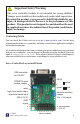
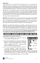
Connecting the Servo Controller The servo controller connections are shown on the facing page, and most of the pins are labeled on the back of the servo controller. Power The servos are typically powered by their own supply consisting of a 4- or 5-cell rechargeable battery pack with a nominal voltage of 4.8-6.0 volts. This supply can be connected to the lower-right corner of the board, or to any of the servo 0 through servo 7 power pins.
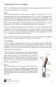
Using the Servo Controller The Pololu servo controller performs the processor-intensive task of simultaneously generating 8 independent servo control signals. The servo controller can generate pulses from 0.25 ms to 2.75 ms, which is greater than the range of most servos, and which allows for a servo operating range of over 180 degrees. Internally, the servo controller maintains a servo position value that is two times the pulse width, measured in microseconds. Thus, the 1.
Interface Options You can communicate with the servo controller using one of two communication protocols. One of the two interface modes is chosen based on the state of mode selection jumper when the servo controller is powered up; you cannot change modes without resetting the servo controller. Pololu Mode: The default mode, when the jumper is open (no shorting block), is a Pololu protocol used for controlling multiple serial devices.
Pololu Mode In this mode, there are several options for controlling your servos. As mentioned at the beginning of this section on page 4, the servo controller holds an internal variable for each servo, the value of which ranges from 500 to 5500, where the number corresponds to the pulse length in increments of half of a microsecond. The various commands deal with setting these internal values. With absolute commands, you simply set the value for each servo.
Pololu Mode (continued) Command 1: Set Speed (1 data byte) This command allows you to set the speed at which the servo moves. If the speed is set to 0 (default), the output pulse will instantly change to the set position. If the speed value is nonzero, the pulse changes gradually from the old position to the new position. With a speed of 1, the pulse width changes at 50 microseconds per second; the maximum speed of 6.35 ms per second is achieved with a speed setting of 127.
Setting and Checking the Servo Numbers The servo controller has the unique feature of allowing the user to set the servo numbers to which the controller responds. By default, the servo controller responds to servo numbers 0-7 (in Pololu mode), but you can set it to respond to numbers 8-15, 1623, all the way to 120-127. (In Mini SSC II mode, the servo controller would respond to numbers 0-15, 16-31, all the way through 240-254.