
User Guide
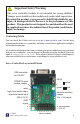

Using the Servo Controller
The Pololu servo controller performs the processor-intensive task of simultaneously
generating 8 independent servo control signals. The servo controller can generate
pulses from 0.25 ms to 2.75 ms, which is greater than the range of most servos, and
which allows for a servo operating range of over 180 degrees.
Internally, the servo controller maintains a servo position value that is two times the
pulse width, measured in microseconds. Thus, the 1.5 ms neutral position, which is
1500 microseconds long, is represented internally as 3000. The internal values range
from 500 to 5500. Various interface modes allow the user to set the position value for
each servo in multiple ways, which are described below.
Serial Input
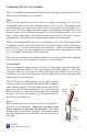
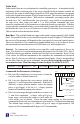
The serial commands sent to the servo controller
must be sent eight bits at a time, with no parity and
one stop bit (sometimes abbreviated 8N1). Logic-
level serial input must be non-inverted, meaning
that a zero is sent as a low voltage, and a one is sent
as a high voltage, as shown in the diagram to the
right. Any inverted serial input, whether at logic
levels or at RS-232 levels, may be connected to the
RS-232 serial input.
When you turn on power with your serial input connected, you should either see all of
the LEDs or just the yellow LED turn on. After the servo controller turns on and
determines the communication mode (see below), it waits for a serial input to
determine the baud rate. If the input line is low, it turns all LEDs on and waits for the
line to go high, which is the idle state for the serial line. Once the line is detected to be
high, only the yellow LED is turned on, and the servo controller waits for a serial input.
If the detected baud rate is too high, the red LED will turn on and the green LED will
flash quickly. If the serial rate is too slow, the red LED will turn on and the yellow LED
will flash. From this point on, the servo controller behavior depends on the
communication mode. Once you choose a baud rate, all subsequent transmissions
must be at that same baud rate.
Indicator LEDs
The green LED indicates serial activity: it should flicker whenever the servo controller
receives data. The yellow LED indicates a warning regarding position: either the
absolute or neutral position you have requested is out of range, or a combination of
neutral, range, and 7-bit or 8-bit position caused the internal position variable to go out
of range. The position will just be limited to the max or min, and the yellow LED will
go out when all requested positions are in range. The red LED indicates a fatal error
that prevents further operation (for example, a fatal error could be caused by invalid
serial input).
4
10011010
start bit stop bit
5V
0V
LSB MSB
© 2006
http://www.pololu.com/
Pololu