
User Manual


int main()
{
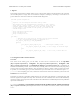
lcd_load_custom_character(happy, 0);
lcd_load_custom_character(sad, 1);
lcd_load_custom_character(indifferent, 2);
lcd_load_custom_character(surprised, 3);
lcd_load_custom_character(mocking, 4);
clear(); // this must be called before we can use the custom characters
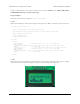
print("mood: ?");
// initialize the random number generator based on how long
// they hold the button the first time
wait_for_button_press(ALL_BUTTONS);
long seed = 0;
while(button_is_pressed(ALL_BUTTONS))
seed++;
srandom(seed);
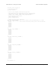
while(1)
{
lcd_goto_xy(6, 0); // move cursor to the correct position
char mood;
do
{
mood = random()%5;
} while (mood == prevMood); // ensure we get a new mood that differs from the previous
prevMood = mood;
print_character(mood); // print a random mood character
wait_for_button(ALL_BUTTONS); // wait for any button to be pressed
}
return 0;
}
3.e. Orangutan LED Control Functions
Overview
These functions allow you to easily control the user LED(s) on the 3pi Robot [https://www.pololu.com/product/
975], Orangutan SV [https://www.pololu.com/product/1227], Orangutan SVP [https://www.pololu.com/product/1325],
Orangutan LV-168 [https://www.pololu.com/product/775], and Baby Orangutan B [https://www.pololu.com/product/
1220]. On the Orangutan SV-xx8 and LV-168, there are two user LEDs are on the top side of the PCB with the red
LED on the bottom left and the green LED on the top right. On the 3pi, there are two user LEDs on the bottom
side of the PCB with the red LED on the right (when looking at the bottom) and the green LED on the left.
Additional LEDs included with the 3pi may be soldered in on the top side (in parallel with the surface-mount
LEDs on the underside) for easier viewing. The Orangutan SVP has two user LEDs: a red LED on the bottom
right and a green LED on the top left. The Baby Orangutan has a single red LED and no green LED.
Note that the red LED is on the same pin as the UART0 serial transmitter (PD1), so if you are using UART0
for serial transmission then the red LED commands will not work, and you will see the red LED blink briefly
whenever data is transmitted on UART0. Note that the green LED is on the same pin as an LCD control pin; the
green LED will blink briefly whenever data is sent to the LCD, but the two functions will otherwise not interfere
with each other.
C++ users: See Section 5.d of Programming Orangutans and the 3pi Robot from the Arduino Environment
[https://www.pololu.com/docs/0J17] for examples of this class in the Arduino environment, which is almost identical
to C++.
Pololu AVR C/C++ Library User’s Guide © 2001–2015 Pololu Corporation
3. Functional Overview and Example programs Page 19 of 43