
User Manual
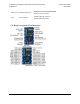


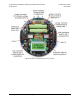

Pin Assignment Table Sorted by Function
Function Arduino Pin mega168 Pin
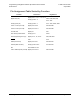
free digital I/Os (x3)
(remove PC5 jumper to free digital pin 19)
digital pins 0, 1, 19 PD0, PD1, PC5
free analog inputs (if you remove jumpers, x3) analog inputs 5 – 7 PC5, ADC6, ADC7
motor 1 (left motor) control (A and B) digital pins 5 and 6 PD5 and PD6
motor 2 (right motor) control (A and B) digital pins 3 and 11 PD3 and PB3
QTR-RC reflectance sensors (left to right, x5) digital pins 14 – 18 PC0 – PC4
red (left) user LED digital pin 1 PD1
green (right) user LED digital pin 7 PD7
user pushbuttons (left to right, x3) digital inputs 9, 12, and 13 PB1, PB4, and PB5
buzzer digital pin 10 PB2
LCD control (RS, R/W, E) digital pins 2, 8, and 4 PD2, PB0, and PD4
LCD data (4-bit: DB4 – DB7) digital pins 9, 12, 13, and 7 PB1, PB4, PB5, and PD7
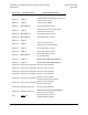
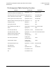
reflectance sensor IR LED control
(drive low to turn IR LEDs off)
digital pin 19
(through jumper)
PC5
user trimmer potentiometer
analog input 7
(through jumper)
ADC7
2/3rds of battery voltage
analog input 6
(through jumper)
ADC6
ICSP programming lines (x3) digital pins 11, 12, and 13 PB3, PB4, PB5
reset pushbutton reset PC6
UART (RX and TX) digital pins 0 and 1 PD0 and PD1
I2C/TWI inaccessable to user
SPI inaccessable to user
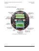
Programming Orangutans and the 3pi Robot from the Arduino
Environment
© 2001–2019 Pololu
Corporation
2. ATmega168/328-Arduino Pin Mapping Page 18 of 66