Pololu 3pi Robot User’s Guide © 2001–2019 Pololu Corporation Pololu 3pi Robot User’s Guide https://www.pololu.
Pololu 3pi Robot User’s Guide 1. Introduction . . . . . . . . . . . . . . . . . . . . . . 2. Contacting Pololu . . . . . . . . . . . . . . . . . . . 3. Important Safety Warning and Handling Precautions 4. Getting Started with Your 3pi Robot . . . . . . . . . 4.a. What You Will Need . . . . . . . . . . . . . . 4.b. Powering Up Your 3pi . . . . . . . . . . . . . 4.c. Using the Preloaded Demo Program . . . . . 4.d. Included Accessories . . . . . . . . . . . . . 5. How Your 3pi Works . . . . . . . . . . . . .
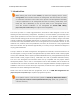
Pololu 3pi Robot User’s Guide © 2001–2019 Pololu Corporation 1. Introduction Note: Starting with serial number 0J5840, 3pi robots are shipping with the newer ATmega328P microcontroller instead of the ATmega168. The serial number is located on a white bar code sticker on the bottom of the 3pi PCB.
Pololu 3pi Robot User’s Guide © 2001–2019 Pololu Corporation 2. Contacting Pololu You can check the 3pi product page [https://www.pololu.com/product/975] for additional information, including pictures, videos, example code, and other resources. We would be delighted to hear from you about any of your projects and about your experience with the 3pi robot. You can contact us [https://www.pololu.com/contact] directly or post on our forum [http://forum.pololu.com/].
Pololu 3pi Robot User’s Guide © 2001–2019 Pololu Corporation 3. Important Safety Warning and Handling Precautions The 3pi robot is not intended for young children! Younger users should use this product only under adult supervision. By using this product, you agree not to hold Pololu liable for any injury or damage related to the use or to the performance of this product.
Pololu 3pi Robot User’s Guide © 2001–2019 Pololu Corporation 4. Getting Started with Your 3pi Robot Getting started with your 3pi can be as simple as taking it out of the box, adding batteries, and turning it on. The 3pi ships with a demo program that will give you a brief tour of its features. General features of the Pololu 3pi robot, top view. 4.
Pololu 3pi Robot User’s Guide © 2001–2019 Pololu Corporation Labeled bottom view of the Pololu 3pi robot. The following subsections will give you all the information you need to get your 3pi up and running! 4.a. What You Will Need The following materials are necessary for getting started with your 3pi: • 4 AAA batteries. Any AAA cells will work, but we recommend NiMH batteries, which are rechargeable and can be purchased from Pololu [https://www.pololu.com/product/1002] or at a local store.
Pololu 3pi Robot User’s Guide © 2001–2019 Pololu Corporation a standard 6-pin programming connector, so your programmer will need to have a 6-pin ISP cable [https://www.pololu.com/product/972] for connecting to the target device. (You will also need whatever cable your programmer requires to connect to a computer. • A desktop or laptop computer. You will need a personal computer for developing your code and loading it onto the 3pi.
Pololu 3pi Robot User’s Guide © 2001–2019 Pololu Corporation potentiometer on the underside of the board. When the program has started successfully, press the B button to proceed to the main menu. Press C or A to scroll forward or backward through the menu, and press B to make a selection or to exit one of the demos. There are seven demos accessible from the menu: 1. Battery: This demo displays the battery voltage in millivolts, which should be above 5000 (5.0 Volts) for a fully-charged set of batteries.
Pololu 3pi Robot User’s Guide © 2001–2019 Pololu Corporation The source code for the demo program is included with the Pololu AVR C/C++ Library described in Section 6, in the folder examples\atmega328p\3pi-demo-program . 4.d. Included Accessories The 3pi robot ships with two through-hole red LEDs and two through-hole green LEDs.
Pololu 3pi Robot User’s Guide © 2001–2019 Pololu Corporation 5. How Your 3pi Works 5.a. Batteries Introduction to Batteries The power system on the 3pi begins with the batteries, so it is important to understand how your batteries work. A battery contains a carefully controlled chemical reaction that pulls electrons in from the positive (+) terminal and pushes them out of the negative (-) terminal.
Pololu 3pi Robot User’s Guide © 2001–2019 Pololu Corporation Battery voltage vs. current. The power put out by a battery is measured by multiplying the volts by the amps, giving a measurement in watts (W). For example, at the point marked in the graph, we have a voltage of 0.9 V and a current of 0.6 A, this means that the power output is 0.54 W. If you want more power, you need to add more batteries, and there are two ways to do it: parallel and series configurations.
Pololu 3pi Robot User’s Guide © 2001–2019 Pololu Corporation Battery voltage vs. time. A rough measure of the amount of energy stored in a battery is given by its milliamp-hour (mAH) rating, which specifies how long the battery will last at a given discharge rate. The mAH rating is the discharge rate multiplied by how long the battery lasts: if you draw current at a rate of 200 mA (0.2 A), and the battery lasts for 3 hours, you would call it a 600 mAH battery.
Pololu 3pi Robot User’s Guide © 2001–2019 Pololu Corporation applications that require a lot of current. For example, 15 V batteries regulated down to 5 V with a linear regulator will lose two-thirds of their energy in the linear regulator. This energy becomes heat, so linear regulators often need large heat sinks, and they generally don’t work well with high-power applications.
Pololu 3pi Robot User’s Guide © 2001–2019 Pololu Corporation a larger motor driver. • Second, since the voltage is regulated, the motors will run the same speed as the batteries drop from 5.5 down to 3.5 V. You can take advantage of this when programming your 3pi, for example by calibrating a 90° turn based on the amount of time that it takes. • Third, at 9.25 V, all five of the IR LEDs can be powered in series so that they consume the lowest possible amount of power.
Pololu 3pi Robot User’s Guide © 2001–2019 Pololu Corporation A motor is a machine that converts electrical energy to motion. There are many different kinds of motors, but the most important for low-cost robotics is the brushed DC motor, which is the type used on the 3pi. A brushed DC motor typically has permanent magnets on the outside and several electromagnetic coils mounted on the motor shaft (armature).
Pololu 3pi Robot User’s Guide © 2001–2019 Pololu Corporation The free-running speed of a small DC motor is usually many thousands of rotations per minute (rpm), much higher than the speed we want the wheels of a robot to turn. A gearbox is a system of gears that converts the high-speed, low-torque output of the motor into a lower-speed, higher-torque output that is a much better suited for driving a robot.
Pololu 3pi Robot User’s Guide © 2001–2019 Pololu Corporation If switches 1 and 4 are closed (the center picture), current flows through the motor from left to right, and the motor spins forward. Closing switches 2 and 3 causes the current to reverse direction and the motor to spin backward. An H-bridge can be constructed with mechanical switches, but most robots, including the 3pi, use transistors to switch the current electronically.
Pololu 3pi Robot User’s Guide © 2001–2019 Pololu Corporation Speed control is achieved by rapidly switching the motor between two states in the table. Suppose we keep PD6 high (at 5 V, also called a logical “1”) and have PD5 alternate quickly between low (0 V or “0”) and high. The motor driver will switch between the “forward” and “brake” states, causing M1 to turn forward at a reduced speed.
Pololu 3pi Robot User’s Guide © 2001–2019 Pololu Corporation The 3pi demonstrating the effects of various motor settings. 5.d. Digital inputs and sensors The microcontroller at the heart of the 3pi, an Atmel AVR mega168 or mega328, has a number of pins which can be configured as digital inputs: they are read by your program as a 1 or a 0 depending on whether the voltage is high (above about 3 V) or low (below about 1.5 V).
Pololu 3pi Robot User’s Guide © 2001–2019 Pololu Corporation up, not a discrete part on the 3pi circuit board. A more complicated use for the digital inputs is in the reflectance sensors. Here is the circuit for the 3pi’s leftmost reflectance sensor, which is connected to pin PC0: The sensing element of the reflectance sensor is the phototransistor shown in the left half of U4, which is connected in series with capacitor C21. A separate connection leads through resistor R12 to pin PC0.
Pololu 3pi Robot User’s Guide © 2001–2019 Pololu Corporation The length of time that the digital input stays at 1 is very short when over white, and very long when over black. The function read_line_sensors() in the Pololu AVR Library switches the port as described above and returns the time for each of the five sensors.
Pololu 3pi Robot User’s Guide © 2001–2019 Pololu Corporation the loop ends, and the time values are returned. 5.e. 3pi Simplified Schematic Diagram A full understanding of how your 3pi works cannot be achieved without first understanding its schematic diagram: 5.
Pololu 3pi Robot User’s Guide 5.
Pololu 3pi Robot User’s Guide © 2001–2019 Pololu Corporation You can download a pdf version of the schematic here [https://www.pololu.com/file/0J119/3pi-schematic.pdf] (481k pdf). 5.
Pololu 3pi Robot User’s Guide © 2001–2019 Pololu Corporation 6. Programming Your 3pi To do more with your 3pi than explore the demo program or use it as a serial slave to a master device, you will need to program it, which requires a computer and an external AVR ISP programmer like our USB AVR programmer v2.1 [https://www.pololu.com/product/3172]. Your programmer’s user’s guide should have all the information you need to get started programming AVRs like the one on the 3pi.
Pololu 3pi Robot User’s Guide © 2001–2019 Pololu Corporation 7. Example Project #1: Line Following 7.a. About Line Following Now that you have learned how to compile a simple program for the 3pi, it’s time to teach your robot do something more complicated. In this example project, we’ll show you how to make your 3pi follow a black line on a white background, by coordinating its sensors and motors.
Pololu 3pi Robot User’s Guide © 2001–2019 Pololu Corporation 1. Calling pololu_3pi_init(2000) to set up the 3pi, with the sensor timeout set to 2000×0.4 us = 800 us. This means that the sensor values will vary from 0 (completely white) to 2000 (completely black), where a value of 2000 indicates that the sensor’s capacitor took at least 800 us to discharge. 2. Displaying the battery voltage returned by the read_battery_millivolts() function.
Pololu 3pi Robot User’s Guide © 2001–2019 Pololu Corporation ◦ 0–1000: the robot is far to the right of the line. In this case, to turn sharply left, we set the right motor speed to 100 and the left motor speed to 0. Note that the maximum speed of the motors is 255, so we are driving the right motor at only about 40% power here. ◦ 1000–3000: the robot is approximately centered on the line. In this case, we set both motors to speed 100, to drive straight ahead.
Pololu 3pi Robot User’s Guide © 2001–2019 Pololu Corporation The entire source code to this simple line following program is presented below, for your reference. 7.
Pololu 3pi Robot User’s Guide 1 2 3 4 5 6 7 8 9 10 11 12 13 14 15 16 17 18 19 20 21 22 23 24 25 26 27 28 29 30 31 32 33 34 35 36 37 38 39 40 41 42 43 44 45 46 47 48 49 50 51 52 53 54 55 56 57 58 59 60 61 62 © 2001–2019 Pololu Corporation /* * 3pi-linefollower - demo code for the Pololu 3pi Robot * * This code will follow a black line on a white background, using a * very simple algorithm.
Pololu 3pi Robot User’s Guide 63 64 65 66 67 68 69 70 71 72 73 74 75 76 77 78 79 80 81 82 83 84 85 86 87 88 89 90 91 92 93 94 95 96 97 98 99 100 101 102 103 104 105 106 107 108 109 110 111 112 113 114 115 116 117 118 119 120 121 122 123 124 © 2001–2019 Pololu Corporation lcd_load_custom_character(levels+2,2); // etc...
Pololu 3pi Robot User’s Guide 125 126 127 128 129 130 131 132 133 134 135 136 137 138 139 140 141 142 143 144 145 146 147 148 149 150 151 152 153 154 155 156 157 158 159 160 161 162 163 164 165 166 167 168 169 170 171 172 173 174 175 176 177 178 179 180 181 182 183 184 185 186 © 2001–2019 Pololu Corporation print_long(bat); print("mV"); lcd_goto_xy(0,1); print("Press B"); delay_ms(100); } // Always wait for the button to be released so that 3pi doesn't // start moving until your hand is away from it.
Pololu 3pi Robot User’s Guide 187 188 189 190 191 192 193 194 195 196 197 198 199 200 201 202 203 204 205 206 207 208 209 210 211 212 213 214 215 216 217 218 219 220 221 222 223 224 225 226 227 228 229 230 231 232 233 234 235 236 237 238 239 240 241 242 243 244 245 © 2001–2019 Pololu Corporation } // This is the main function, where the code starts. All C programs // must have a main() function defined somewhere.
Pololu 3pi Robot User’s Guide © 2001–2019 Pololu Corporation 7.c. Advanced Line Following with 3pi: PID Control A more advanced line following program for the 3pi is available in the folder linefollower-pid . examples\atmegaxx8\3pi- Note: An Arduino-compatible version of this sample program can be downloaded as part of the Pololu Arduino Libraries [https://www.pololu.com/docs/0J17] (see Section 5.g).
Pololu 3pi Robot User’s Guide © 2001–2019 Pololu Corporation negative overflow. In this particular case, it actually wouldn’t affect the results, but it is always a good idea to use casting to avoid unexpected behavior. Each of these input values provides a different kind of information.
Pololu 3pi Robot User’s Guide © 2001–2019 Pololu Corporation 8. Example Project #2: Maze Solving 8.a. Solving a Line Maze The next step up from simple line following is to teach your 3pi to navigate paths with sharp turns, dead ends, and intersections. Make a complicated network of intersecting black lines, add a circle to represent the goal, and you have a line maze, which is a challenging environment for a robot to explore.
Pololu 3pi Robot User’s Guide © 2001–2019 Pololu Corporation Note: An Arduino-compatible version of this sample program can be downloaded as part of the Pololu Arduino Libraries [https://www.pololu.com/docs/0J17] (see Section 5.g) The Arduino sample sketch is all contained within a single file. This program is much more complicated than the examples you have seen so far, so we have split it up into multiple files. Using multiple files makes it easier for you to keep track of your code.
Pololu 3pi Robot User’s Guide © 2001–2019 Pololu Corporation This line declares the turn() function without actually including a copy of its code. To access the declaration, each C file that needs to call turn() adds the following line: 1 #include "turn.h" ? Note the double-quotes being used instead of angle brackets. This signifies to the C compiler that the header file is in the project directory, rather than being a system header file like 3pi.h .
Pololu 3pi Robot User’s Guide 1 2 3 4 5 6 7 8 9 10 11 12 13 14 15 16 17 18 19 20 21 22 23 24 25 26 27 28 29 30 31 32 33 34 35 36 37 38 39 40 41 42 43 44 45 46 47 48 49 50 51 52 53 54 55 56 57 58 59 60 61 62 © 2001–2019 Pololu Corporation void follow_segment() { int last_proportional = 0; long integral=0; ? while(1) { // Normally, we will be following a line. The code below is // similar to the 3pi-linefollower-pid example, but the maximum // speed is turned down to 60 for reliability.
Pololu 3pi Robot User’s Guide 63 64 65 © 2001–2019 Pololu Corporation } } Between the PID code and the intersection detection, there are now about six more parameters that could be adjusted. We’ve picked values here that allow 3pi to solve the maze at a safe, controlled speed; try increasing the speed and you will quickly run in to lots of problems that you’ll have to handle with more complicated code. Putting the C files and header files into your project is easy with Atmel Studio.
Pololu 3pi Robot User’s Guide © 2001–2019 Pololu Corporation 8.d. The Main Loop(s) The strategy of our program is expressed in the file maze-solve.c . Most importantly, we want to keep track of the path that we have followed, so we define an array storing up to 100; these will be the same characters used in the turn() function. We also need to keep track of the current path length so that we know where to put the characters in the array.
Pololu 3pi Robot User’s Guide 1 2 3 4 5 6 7 8 9 10 11 12 13 14 15 16 17 18 19 20 21 22 23 24 25 26 27 28 29 30 31 32 33 34 35 36 37 38 39 40 41 42 43 44 45 46 47 48 49 50 51 52 53 54 55 56 57 58 59 60 61 62 © 2001–2019 Pololu Corporation // FIRST MAIN LOOP BODY follow_segment(); ? // Drive straight a bit. This helps us in case we entered the // intersection at an angle. // Note that we are slowing down - this prevents the robot // from tipping forward too much.
Pololu 3pi Robot User’s Guide 63 64 © 2001–2019 Pololu Corporation // Display the path on the LCD. display_path(); We’ll discuss the call to simplify_path() in the next section. Before that, let’s take a look at the second main loop, which is very simple. All we do is drive to the next intersection and turn according to our records. After doing the last recorded turn, the robot will be one segment away from the finish, which explains the final follow_segment() call in the outline of maze_solve() above.
Pololu 3pi Robot User’s Guide © 2001–2019 Pololu Corporation Another example is a T-intersection with a dead end on the left: ‘LBS’. The turns are 90° left, 180°, and 0°, for a total of 90° right. The sequence should be replaced with a single ‘R’. In fact, whenever we have a sequence like ‘xBx’, we can replace all three turns with a turn corresponding to the total angle, eliminating the U-turn and speeding up our solution. Here’s the code to handle this: 8.
Pololu 3pi Robot User’s Guide 1 2 3 4 5 6 7 8 9 10 11 12 13 14 15 16 17 18 19 20 21 22 23 24 25 26 27 28 29 30 31 32 33 34 35 36 37 38 39 40 41 42 43 44 45 46 47 48 49 50 51 © 2001–2019 Pololu Corporation // Path simplification. The strategy is that whenever we encounter a // sequence xBx, we can simplify it by cutting out the dead end. For // example, LBL -> S, because a single S bypasses the dead end // represented by LBL.
Pololu 3pi Robot User’s Guide © 2001–2019 Pololu Corporation explore it: Fully explore the maze using a left-hand-on-the-wall strategy. The above list of actions is a record of all the steps we took to fully explore the maze while looking for the end, which is marked by the large black circle. Our goal is to now reduce this list to represent the shortest path from start to finish by weeding out all of the dead ends.
Pololu 3pi Robot User’s Guide © 2001–2019 Pololu Corporation When we encounter the first intersection after our first “back” action, we know we have reached a dead end that can be removed from our list of actions. In this case, the most recent actions in our list is the sequence ‘SBL’, and the diagram shows that this sequence can be simplified into a single right turn ‘R’. Prune out the rest of this dead-end branch as we back-track. 8.
Pololu 3pi Robot User’s Guide © 2001–2019 Pololu Corporation We next end up with the sequence ‘RBL’, which reduces to a single back ‘B’, and this combines with the next action to produce the sequence ‘LBL’, which reduces to a single straight ‘S’. Prune out the final dead-end branch to leave us with the shortest path from start to finish. 8.
Pololu 3pi Robot User’s Guide © 2001–2019 Pololu Corporation The last dead end gives us the sequence ‘SBL’, which reduces to a sigle right turn ‘R’. Our action list is now just ‘R’ and represents the shortest path from start to finish. As we drove the maze, our action list would have looked like the following: 1. L 2. LS 3. LSB 4. LSBL => LR (pruning occurs here) 5. LRB 6. LRBL => LB (pruning occurs here) 7. LBL => S (pruning occurs here) 8. SB 9. SBL => R (pruning occurs here) 8.
Pololu 3pi Robot User’s Guide © 2001–2019 Pololu Corporation 8.f. Improving the Maze-Solving Code We have gone over the most important parts of the code; the other bits and pieces (like the function display_path(), the start-up sequence and calibration, etc.) can be found with everything else in the folder examples\atmegaxx8\3pi-mazesolver . After you have the code working and you understand it well, you should try to improve your robot to be as fast as possible.
Pololu 3pi Robot User’s Guide © 2001–2019 Pololu Corporation
An error occurred.
Pololu 3pi Robot User’s Guide © 2001–2019 Pololu Corporation directly led to that intersection. The units of the segment times were chosen to provide numbers that can allow the robot to meaningfully differentiate between longer and shorter segments but that never exceed 255 for any segment in the maze. This second restriction means that the values can be stored in an array of unsigned chars (i.e. each segment’s time takes up just one byte of memory), which helps keep memory usage down.
Pololu 3pi Robot User’s Guide © 2001–2019 Pololu Corporation 9. Pin Assignment Tables General features of the Pololu 3pi robot, top view. 9.
Pololu 3pi Robot User’s Guide © 2001–2019 Pololu Corporation Labeled bottom view of the Pololu 3pi robot. 9.
Pololu 3pi Robot User’s Guide © 2001–2019 Pololu Corporation Specific features of the Pololu 3pi robot, top view. 9.
Pololu 3pi Robot User’s Guide © 2001–2019 Pololu Corporation Pin Assignment Table Sorted by Function Function free digital I/Os (x3) ATmegaxx8 Pin Arduino Pin PD0, PD1, PC5 digital pins 0, 1, 19 free analog inputs (if you remove jumpers, x3) PC5, ADC6, ADC7 analog inputs 5 – 7 motor 1 (left motor) control (A and B) PD5 and PD6 digital pins 5 and 6 motor 2 (right motor) control (A and B) PD3 and PB3 digital pins 3 and 11 QTR-RC reflectance sensors (left to right, x5) PC0 – PC4 digital pins
Pololu 3pi Robot User’s Guide © 2001–2019 Pololu Corporation Pin Assignment Table Sorted by Pin 9.
Pololu 3pi Robot User’s Guide ATmegaxx8 Pin © 2001–2019 Pololu Corporation 3pi Function Notes/Alternate Functions PD0 free digital I/O PD1 free digital I/O PD2 LCD control line RS external interrupt 0 (INT0) PD3 M2 control line Timer2 PWM output B (OC2B) PD4 LCD control line E PD5 M1 control line Timer0 PWM output B (OC0B) PD6 M1 control line Timer0 PWM output A (OC0A) PD7 LCD data line DB7 connected to green user LED (high turns LED on) PB0 LCD control line R/W PB1 LCD data lin
Pololu 3pi Robot User’s Guide PC5 ADC6 ADC7 reset © 2001–2019 Pololu Corporation analog input and jumpered to sensors’ IR LEDs (driving low turns off emitters) digital I/O ADC input channel 5 (ADC5) dedicated analog input jumpered to 2/3rds of battery voltage ADC input channel 6 (ADC6) dedicated analog jumpered to user trimmer potentiometer ADC input channel 7 input (ADC7) reset pushbutton internally pulled high; active low digital I/O disabled by default 9.
Pololu 3pi Robot User’s Guide © 2001–2019 Pololu Corporation 10. Expansion Information 10.a. Serial slave program The Pololu AVR library (see Section 6) comes with an example serial slave program for the 3pi in libpololu-avr\examples\atmegaxx8\3pi-serial-slave , and a corresponding serial master program in libpololu-avr\examples\atmegaxx8\3pi-serial-master . This example shows how to use a ring buffer in SERIAL_CHECK mode to continuously receive and interpret a simple set of commands.
Pololu 3pi Robot User’s Guide We also offer a more advanced expansion kit © 2001–2019 Pololu Corporation [https://www.pololu.com/product/2152] that lets you turn your 3pi robot into an m3pi robot. The m3pi expansion kit has sockets for additional electronics, making it simple to significantly increase the capabilities of your 3pi. One socket let’s you use a powerful mbed development board [https://www.pololu.
Pololu 3pi Robot User’s Guide © 2001–2019 Pololu Corporation are no parity bits, 8 data bits, and one stop bit (N81). The commands implemented here each consist of a single command byte followed by zero or more data bytes. To make it easy to differentiate the command bytes from the data bytes, the command bytes are all in the range 0x80-0xff, while the data bytes are in the range 0x00-0x7f. That is, the command bytes have their most significant bits set, while the data bytes have that bit unset.
Pololu 3pi Robot User’s Guide Command byte Command © 2001–2019 Pololu Corporation Data Response bytes bytes Description 0x81 signature 0 6 Sends the slave name and code version, e.g. “3pi1.0”. This command also sets motor speeds to 0 and stops PID line following, if active, so it is useful as an initialization command.
Pololu 3pi Robot User’s Guide © 2001–2019 Pololu Corporation 0xB6 line position 0 2 Reads all five IR sensors using calibrated values and estimates the position of a black line under the robot. The value, which is sent back as a two-byte integer, is 0 when the line is under sensor PC0 or farther to the left, 1000 when the line is directly under sensor PC1, up to 4000 when it is under sensor PC4 or farther to the right.
Pololu 3pi Robot User’s Guide © 2001–2019 Pololu Corporation of 0 (off) up to 127 (full speed). 0xC2 M1 backward 1 0 Sets motor M1 turning backward with a speed of 0 (off) up to 127 (full reverse). 0xC5 M2 forward 1 0 Sets motor M2 turning forward with a speed of 0 (off) up to 127 (full speed). 0xC6 M2 backward 1 0 Sets motor M2 turning backward with a speed of 0 (off) up to 127 (full reverse). 10.
Pololu 3pi Robot User’s Guide © 2001–2019 Pololu Corporation Source code 10.
Pololu 3pi Robot User’s Guide 1 2 3 4 5 6 7 8 9 10 11 12 13 14 15 16 17 18 19 20 21 22 23 24 25 26 27 28 29 30 31 32 33 34 35 36 37 38 39 40 41 42 43 44 45 46 47 48 49 50 51 52 53 54 55 56 57 58 59 60 61 62 © 2001–2019 Pololu Corporation ? #include /* * 3pi-serial-slave - An example serial slave program for the Pololu * 3pi Robot. See the following pages for more information: * * http://www.pololu.com/docs/0J21 * http://www.pololu.com/docs/0J20 * http://www.poolu.
Pololu 3pi Robot User’s Guide 63 64 65 66 67 68 69 70 71 72 73 74 75 76 77 78 79 80 81 82 83 84 85 86 87 88 89 90 91 92 93 94 95 96 97 98 99 100 101 102 103 104 105 106 107 108 109 110 111 112 113 114 115 116 117 118 119 120 121 122 123 124 © 2001–2019 Pololu Corporation if(power_difference < 0) set_motors(max_speed+power_difference, max_speed); else set_motors(max_speed, max_speed-power_difference); } // A global ring buffer for data coming in.
Pololu 3pi Robot User’s Guide 125 126 127 128 129 130 131 132 133 134 135 136 137 138 139 140 141 142 143 144 145 146 147 148 149 150 151 152 153 154 155 156 157 158 159 160 161 162 163 164 165 166 167 168 169 170 171 172 173 174 175 176 177 178 179 180 181 182 183 184 185 186 © 2001–2019 Pololu Corporation char check_data_byte(char byte) { if(is_data(byte)) return 0; play("o3c"); clear(); print("Bad data"); lcd_goto_xy(0,1); print_hex_byte(byte); previous_byte(); return 1; } ////////////////////////////
Pololu 3pi Robot User’s Guide 187 188 189 190 191 192 193 194 195 196 197 198 199 200 201 202 203 204 205 206 207 208 209 210 211 212 213 214 215 216 217 218 219 220 221 222 223 224 225 226 227 228 229 230 231 232 233 234 235 236 237 238 239 240 241 242 243 244 245 246 247 248 © 2001–2019 Pololu Corporation // function, and sends the value. // Returns the last value computed if PID is running.
Pololu 3pi Robot User’s Guide 249 250 251 252 253 254 255 256 257 258 259 260 261 262 263 264 265 266 267 268 269 270 271 272 273 274 275 276 277 278 279 280 281 282 283 284 285 286 287 288 289 290 291 292 293 294 295 296 297 298 299 300 301 302 303 304 305 306 307 308 309 310 © 2001–2019 Pololu Corporation set_m1_speed(byte == 127 ? -255 : -byte*2); } // Drives m2 backward.
Pololu 3pi Robot User’s Guide 311 312 313 314 315 316 317 318 319 320 321 322 323 324 325 326 327 328 329 330 331 332 333 334 335 336 337 338 339 340 341 342 343 344 345 346 347 348 349 350 351 352 353 354 355 356 357 358 359 360 361 362 363 364 365 366 367 368 369 370 371 372 © 2001–2019 Pololu Corporation character = read_next_byte(); if(check_data_byte(character)) return; // Before printing to the LCD we need to go to AUTOMATIC mode.
Pololu 3pi Robot User’s Guide 373 374 375 376 377 378 379 380 381 382 383 384 385 386 387 388 389 390 391 392 393 394 395 396 397 398 399 400 401 402 403 404 405 406 407 408 409 410 411 412 413 414 415 416 417 418 419 420 421 422 423 424 425 426 427 428 429 430 431 432 433 434 © 2001–2019 Pololu Corporation p_den = constants[2]; d_num = constants[3]; d_den = constants[4]; // enable pid pid_enabled = 1; } // Turns off PID void stop_pid() { set_motors(0,0); pid_enabled = 0; } //////////////////////////////
Pololu 3pi Robot User’s Guide 435 436 437 438 439 440 441 442 443 444 445 446 447 448 449 450 451 452 453 454 455 456 457 458 459 460 461 462 463 464 465 466 467 468 469 470 471 472 473 474 475 476 477 478 479 480 481 482 483 484 485 486 487 © 2001–2019 Pololu Corporation case (char)0xB4: calibrate_line_sensors(IR_EMITTERS_ON); send_calibrated_sensor_values(1); break; case (char)0xB5: line_sensors_reset_calibration(); break; case (char)0xB6: send_line_position(); break; case (char)0xB7: do_clear(); break
Pololu 3pi Robot User’s Guide [https://www.pololu.com/product/775], © 2001–2019 Pololu Corporation or 3pi as a demonstration of what is possible, but you will probably want to adapt it for your own controller. To use the program, make the following connections between your master and slave: • GND-GND • PD0-PD1 • PD1-PD0 Turn on both master and slave. The master will display a “Connect” message followed by the signature of the slave source code (e.g. “3pi1.0”).
Pololu 3pi Robot User’s Guide © 2001–2019 Pololu Corporation Source code 10.
Pololu 3pi Robot User’s Guide 1 2 3 4 5 6 7 8 9 10 11 12 13 14 15 16 17 18 19 20 21 22 23 24 25 26 27 28 29 30 31 32 33 34 35 36 37 38 39 40 41 42 43 44 45 46 47 48 49 50 51 52 53 54 55 56 57 58 59 60 61 62 © 2001–2019 Pololu Corporation #include #include ? /* * 3pi-serial-master - An example serial master program for the Pololu * 3pi Robot. This can run on any board supported by the library; * it is intended as an example of how to use the master/slave * routines.
Pololu 3pi Robot User’s Guide 63 64 65 66 67 68 69 70 71 72 73 74 75 76 77 78 79 80 81 82 83 84 85 86 87 88 89 90 91 92 93 94 95 96 97 98 99 100 101 102 103 104 105 106 107 108 109 110 111 112 113 114 115 116 117 118 119 120 121 122 123 124 © 2001–2019 Pololu Corporation // The variable c will have values from 0 to 9, since // values are in the range of 0 to 1000, and 1000/101 is 9 // with integer math. char c = bar_graph_characters[sensors[i]/101]; // Display the bar graph characters.
Pololu 3pi Robot User’s Guide 125 126 127 128 129 130 131 132 133 134 135 136 137 138 139 140 141 142 143 144 145 146 147 148 149 150 151 152 153 154 155 156 157 158 159 160 161 162 163 164 165 166 167 168 169 170 171 172 173 174 175 176 177 178 179 180 181 182 183 184 185 186 © 2001–2019 Pololu Corporation // stops the pid line following void slave_stop_pid() { serial_send_blocking("\xBC", 1); } // clear the slave LCD void slave_clear() { serial_send_blocking("\xB7",1); } // print to the slave LCD void
Pololu 3pi Robot User’s Guide 187 188 189 190 191 192 193 194 195 196 197 198 199 200 201 202 203 204 205 206 207 208 209 210 211 212 213 214 215 216 217 218 219 220 221 222 223 224 225 226 227 228 229 230 231 232 233 234 235 236 237 238 239 240 241 242 243 244 245 246 247 248 © 2001–2019 Pololu Corporation slave_print("OK"); // play a tune char tune[] = "\xB3 l16o6gab>c"; tune[1] = sizeof(tune)-3; serial_send_blocking(tune,sizeof(tune)-1); // wait wait_for_button(ALL_BUTTONS); // reset calibration slave
Pololu 3pi Robot User’s Guide 249 250 251 252 253 254 255 256 257 258 259 260 261 262 263 264 265 266 267 268 269 270 271 272 273 274 © 2001–2019 Pololu Corporation else if(speed1 > 1) speed1 -= 2; else if(speed1 > 0) speed1 = 0; // if button C is pressed, control motor2 if(button_is_pressed(BUTTON_C) && speed2 < 127) speed2 ++; else if(speed2 > 1) speed2 -= 2; else if(speed2 > 0) speed2 = 0; // if button B is pressed, do PID control if(button_is_pressed(BUTTON_B)) slave_set_pid(40, 1, 20, 3, 2); else {
Pololu 3pi Robot User’s Guide © 2001–2019 Pololu Corporation trimmer potentiometer when its shorting block is in place. Note: If you call the Pololu AVR library’s sensor reading functions, the 3pi will drive pin PC5 high for the duration of the sensor read, and it will then drive pin PC5 low. It does this even if the PC5 shorting block is removed. If this behavior will interfere with what you want to connect to PC5, you can modify the library code to initialize the sensors with a bogus emitter pin (e.g.
Pololu 3pi Robot User’s Guide © 2001–2019 Pololu Corporation 11. Related Resources To learn more about using the Pololu 3pi Robot, see the following list of resources: • Pololu AVR Programming Quick Start Guide [https://www.pololu.com/docs/0J51]: tutorials on how to get started programming in Windows, Linux, and Mac OS X. • Pololu AVR Library Command Reference [https://www.pololu.com/docs/0J18]: detailed information about every function in the library.
Pololu 3pi Robot User’s Guide © 2001–2019 Pololu Corporation 12. Revision History and Errata • 3pi robots with serial numbers less than 0J7259 have AREF connected to AVCC. This makes it unsafe to configure the AVR’s ADC to use the internal voltage reference. Newer 3pi robots disconnect AREF from AVCC and add capacitor C32 between AREF and GND, making it safe to use the internal voltage reference. 12.