Sample Project: RC 3pi © 2001–2019 Pololu Corporation Sample Project: RC 3pi 1. Introduction . . . . . . . . 2. Materials and Tools . . . . 3. Construction . . . . . . . 4. Software . . . . . . . . . 5. Suggested Improvements 6. Conclusion . . . . . . . . . . . . . . . . . . . . . . . . . . https://www.pololu.com/docs/0J37/all . . . . . . . . . . . . . . . . . . . . . . . . . . . . . . . . . . . . . . . . . . . . . . . . . . . . . . . . . . . . . . . . . . . . . . . . . . . . . . . . .
Sample Project: RC 3pi © 2001–2019 Pololu Corporation 1. Introduction 1.
Sample Project: RC 3pi 1.
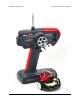
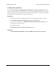
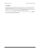
Sample Project: RC 3pi © 2001–2019 Pololu Corporation A radio-controlled 3pi with an RC transmitter. The 3pi robot [https://www.pololu.com/product/975] is complete mobile platform designed to excel in linefollowing and maze-solving competitions. The 3pi has user accessible I/O lines that can be connected to different sensors to expand its behavior beyond line-following and maze-solving.
Sample Project: RC 3pi © 2001–2019 Pololu Corporation 2. Materials and Tools Beyond the Pololu 3pi robot + USB programmer combo [https://www.pololu.com/product/1306], you will need a few other materials for this project. You only need the materials listed under the “required” section to make the RC 3pi work, but the optional header makes it easier to reconfigure your 3pi with other sensors later by allowing you to unplug your RC receiver.
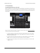
Sample Project: RC 3pi © 2001–2019 Pololu Corporation 3. Construction Connecting the Receiver to the 3pi Begin by soldering the 2×7 female header where it fits between the 3pi’s gearmotors, as shown in the picture below. If you do not have the header, you can still build an RC 3pi; you will need to solder the wires directly to the 3pi’s circuit board in the places where they would have been inserted into the female header. A 2×7 female header soldered into the 3pi expansion pin holes.
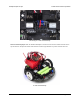
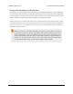
Sample Project: RC 3pi © 2001–2019 Pololu Corporation The wiring of a radio-controlled 3pi. Remove the PC5 jumper and use double-sided tape to secure the RC receiver and its antenna to the 3pi as shown in the picture below. Note that the receiver might fit better if you first remove the LCD. A radio-controlled 3pi. 3.
Sample Project: RC 3pi © 2001–2019 Pololu Corporation Design Considerations and Restrictions In this project, we used pins PD0 and PC5 because they are available digital inputs. We avoided using PD1 because the LED on that line can pull the signal down and lead to poor performance, depending on how strongly the receiver drives its outputs. ADC6 and ADC7 can only be used as analog inputs and are not ideal for measuring the widths of digital pulses with good accuracy.
Sample Project: RC 3pi © 2001–2019 Pololu Corporation 4. Software The final step is to insert fresh batteries into your 3pi and use an AVR ISP programmer (like our USB AVR programmer [https://www.pololu.com/product/1300]) to program it with the following code. For information on programming your 3pi, please visit the programming your 3pi docs/0J21/6] [http://www.pololu.com/ section of the 3pi robot user’s guide [http://www.pololu.com/docs/0J21].
Sample Project: RC 3pi 1 2 3 4 5 6 7 8 9 10 11 12 13 14 15 16 17 18 19 20 21 22 23 24 25 26 27 28 29 30 31 32 33 34 35 36 37 38 39 40 41 42 43 44 45 46 47 48 49 50 51 52 53 54 55 56 57 58 59 60 61 62 © 2001–2019 Pololu Corporation /** * RC 3pi * * This 3pi robot program reads two standard radio-control (RC) channels and mixes * them into motor control. Channel zero (connected to the PD0 input) * handles forward and reverse, and channel one (connected to the * PC5 input) handles turning.
Sample Project: RC 3pi 63 64 65 66 67 68 69 70 71 72 73 74 75 76 77 78 79 80 81 82 83 84 85 86 87 88 89 90 91 92 93 94 95 96 97 98 99 100 101 102 103 104 105 106 107 108 109 110 111 112 113 114 115 116 117 118 119 120 121 122 123 124 © 2001–2019 Pololu Corporation // Save a snapshot of PIND at the current time unsigned char pind = PIND; unsigned int time = TCNT1; if (pind & (1 << PORTD0)) { // PD0 has changed to high so record the low pulse's duration ch[0].lowDur = time - ch[0].
Sample Project: RC 3pi 125 126 127 128 129 130 131 132 133 134 135 136 137 138 139 140 141 142 143 144 145 146 147 148 149 150 151 152 153 154 155 156 157 158 159 160 161 162 163 164 165 166 167 168 169 170 171 172 173 174 175 176 177 178 179 180 181 182 183 184 185 186 © 2001–2019 Pololu Corporation cli(); // Disable interrupts while reading highDur and lowDur ch[i].newPulse = 0; unsigned int highDuration = ch[i].highDur; unsigned int lowDuration = ch[i].lowDur; sei(); // Enable interrupts ch[i].
Sample Project: RC 3pi 187 188 189 190 191 192 193 194 195 196 197 198 199 200 201 202 203 204 205 206 207 208 209 210 211 212 213 214 215 216 217 218 219 220 221 222 223 224 225 226 227 228 229 230 231 232 233 234 235 236 237 238 239 240 241 242 © 2001–2019 Pololu Corporation print("ch1 "); // Multiplying by 32/10 converts ticks to microseconds print_unsigned_long(ch[0].pulse * 32 / 10); print(" "); lcd_goto_xy(0, 1); print("ch2 "); print_unsigned_long(ch[1].pulse * 32 / 10); } if (ch[0].error || ch[1].
Sample Project: RC 3pi © 2001–2019 Pololu Corporation You can then use the trim settings on your transmitter to adjust the neutral points to 1.5 ms, or you can modify the neutral points in the code. You also might want to characterize the ranges of the pulses and adjust the motor speed scaling so that the motors reach full speed when the transmitter sticks are at their full extents. Lastly, you might need to change some of the signs in the channel mixing formulas so that the robot responds intuitively (e.
Sample Project: RC 3pi © 2001–2019 Pololu Corporation 5. Suggested Improvements • Program the 3pi to automatically measure the neutral, maximum, and minimum value of each channel so that responds better to the transmitter. Doing this will ensure that the robot is at a full stop when the transmitter sticks are in their neutral positions and that the motors reach full speed appropriately when the sticks are at the ends of their ranges.
Sample Project: RC 3pi © 2001–2019 Pololu Corporation 6. Conclusion With the addition of an RC receiver and some simple code, the 3pi can become a radio-controlled robot with a nice speed and excellent turning ability. We encourage you to try to improve upon this project by adding more sensors [https://www.pololu.com/category/7/sensors] or even by merely enhancing the code. Please join us on our robotics forum [http://forum.pololu.com/viewforum.