Sample Project: RC 3pi © 2001–2009 Pololu Corporation Sample Project: RC 3pi 1. Introduction . . . . . . . 2. Materials and Tools . . . 3. Construction . . . . . . 4. Software . . . . . . . . 5. Suggested Improvements 6. Conclusion . . . . . . . . . . . . . . . . . . . . . . . . . . . . . . . . . . . . . . . . . . . . . . . . . . . . . . . . . . . . . . . . . . . . . . . . . . . . . . . . . . . . . . . . . . . . . . . . . . . . . . . . . . . . . . . . . . . . . . . . . . . . . . . .
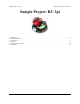
Sample Project: RC 3pi © 2001–2009 Pololu Corporation 1. Introduction A radio-controlled 3pi with an RC transmitter. The 3pi robot [http://www.pololu.com/catalog/product/975] is complete mobile platform designed to excel in linefollowing and maze-solving competitions. The 3pi has user accessible I/O lines that can be connected to different sensors to expand its behavior beyond line-following and maze-solving.
Sample Project: RC 3pi © 2001–2009 Pololu Corporation 2. Materials and Tools Beyond the Pololu 3pi robot + USB programmer combo [http://www.pololu.com/catalog/product/1306], you will need a few other materials for this project. You only need the materials listed under the “required” section to make the RC 3pi work, but the optional header makes it easier to reconfigure your 3pi with other sensors later by allowing you to unplug your RC receiver.
Sample Project: RC 3pi © 2001–2009 Pololu Corporation 3. Construction Connecting the Receiver to the 3pi Begin by soldering the 2×7 female header where it fits between the 3pi’s gearmotors, as shown in the picture below. If you do not have the header, you can still build an RC 3pi; you will need to solder the wires directly to the 3pi’s circuit board in the places where they would have been inserted into the female header. A 2×7 female header soldered into the 3pi expansion pin holes.
Sample Project: RC 3pi © 2001–2009 Pololu Corporation A radio-controlled 3pi. Design Considerations and Restrictions In this project, we used pins PD0 and PC5 because they are available digital inputs. We avoided using PD1 because the LED on that line can pull the signal down and lead to poor performance, depending on how strongly the receiver drives its outputs. ADC6 and ADC7 can only be used as analog inputs and are not ideal for measuring the widths of digital pulses with good accuracy.
Sample Project: RC 3pi © 2001–2009 Pololu Corporation 4. Software The final step is to insert fresh batteries into your 3pi and use an AVR ISP programmer (like our USB AVR programmer [http://www.pololu.com/catalog/product/1300]) to program it with the following code. For information on programming your 3pi, please visit the programming your 3pi [http://www.pololu.com/docs/0J21/6] section of the 3pi robot user’s guide [http://www.pololu.com/docs/0J21].
Sample Project: RC 3pi { } © 2001–2009 Pololu Corporation // Save a snapshot of PIND at the current time unsigned char pind = PIND; unsigned int time = TCNT1; if (pind & (1 << PORTD0)) { // PD0 has changed to high so record the low pulse's duration ch[0].lowDur = time - ch[0].prevTime; } else { // PD0 has changed to low so record the high pulse's duration ch[0].highDur = time - ch[0].prevTime; ch[0].newPulse = 1; // The high pulse just finished so we can process it now } ch[0].
Sample Project: RC 3pi else { } } } } © 2001–2009 Pololu Corporation // Wait for error number of good pulses if (ch[i].error) ch[i].error--; else { // Save the duration of the high pulse for use in the channel mixing // calculation below ch[i].pulse = highDuration; } int main() { ch[0].error = 5; // Wait for 5 good pulses before trusting the signal ch[1].
Sample Project: RC 3pi } } // // // // // // // // } © 2001–2009 Pololu Corporation * Your transmitter/receiver might treat channels 0 and 1 differently * than the receiver this code was developed for. If your 3pi turns * when you expect it to go straight or vice versa, you may need to flip * a sign in the calculation below or swap the connections at the receiver. * */ long m1 = (neutralPulseTime - (int)ch[0].pulse) + ((int)ch[1].pulse - neutralPulseTime); long m2 = (neutralPulseTime - (int)ch[0].
Sample Project: RC 3pi © 2001–2009 Pololu Corporation 5. Suggested Improvements • Program the 3pi to automatically measure the neutral, maximum, and minimum value of each channel so that responds better to the transmitter. Doing this will ensure that the robot is at a full stop when the transmitter sticks are in their neutral positions and that the motors reach full speed appropriately when the sticks are at the ends of their ranges.
Sample Project: RC 3pi © 2001–2009 Pololu Corporation 6. Conclusion With the addition of an RC receiver and some simple code, the 3pi can become a radio-controlled robot with a nice speed and excellent turning ability. We encourage you to try to improve upon this project by adding more sensors [http://www.pololu.com/catalog/category/7] or even by merely enhancing the code. Please join us on our robotics forum [http://forum.pololu.com/viewforum.