
Manual


However, a higher PWM frequency means greater power loss due to switching, which could make a 5 kHz PWM
frequency a better choice for certain applications.
Additionally, the 5 kHz PWM frequency allows for finer control at duty cycles approaching 0% or 100% (±600). This
is because the timing characteristics of the jrk motor drivers make it so that very short PWM pulses (either low or
high) have no effect on the output voltage. This limitation is more pronounced on the jrk 21v3, in which pulses that
are shorter than approximately 4 μs have no effect on the output voltage. Therefore, at 20 kHz, the jrk 21v3 with a
duty cycle less than 8% will effectively have a duty cycle of 0% (braking), while a duty cycle greater than 92% will
be the same as a duty cycle of 100% (the jrk 12v12 can typically go a bit closer to 0% and 100%). At 5 kHz, the effect
is smaller by a factor of four: a duty cycle less than 2% will be the same as a duty cycle of 0% (braking) while a duty
cycle greater than 98% will be the same as a duty cycle of 100%.
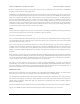
Limits
Various limits may be applied to the duty cycle, each of which can be configured separately for forward (positive duty
cycle) and reverse (negative duty cycle) if the “Asymmetric” option is checked:
Max. duty cycle limits the duty cycle itself.
Max. acceleration limits the amount that the duty cycle can change by in a single PID period. For example, if there
is an acceleration limit of 10 in both directions, and the current duty cycle is 300, then the duty cycle in the next PID
period is limited to be within -10 to 310.
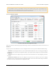
Max. current causes the jrk to measure the motor driver current and adjust the duty cycle as necessary to limit it the
specified value. The current is reported as a number from 0 to 255 that is multiplied by the Current calibration to get
a number in mA, so increasing the current calibration value will increase the measured value. For accurate current
limiting, acceleration should be limited; otherwise the duty cycle will tend to oscillate when the maximum current is
exceeded.
Brake duration is a feature that is most useful for large motors with high-inertia loads used with frequency feedback
or speed control mode (no feedback). If this option is used, the jrk will automatically keep the motor at a duty cycle
of 0 for the specified time before switching directions. The “forward” setting refers to switching from forward to
reverse, and the “reverse” setting refers to switching from reverse to forward.
Max. duty cycle while feedback is out of range is an option to limit possible damage to systems by reducing the
maximum duty cycle whenever the feedback value is beyond the absolute minimum and maximum values. This can
be used, for example, to slowly bring a system back into its valid range of operation when it is dangerously near a
limit. The Feedback disconnect error should be disabled when this option is used.
When motor is off
When the motor is off because of an error condition or an explicit Motor Off command, there are two options for the
state of the motor driver: brake (A and B both connected to GND) and coast (A and B floating).
You can familiarize yourself with motor coasting and braking using nothing more than a motor. First, with your motor
disconnected from anything, try rotating the output shaft and note how easily it turns. Then hold the two motor leads
together and try rotating the output shaft again. You should notice significantly more turning resistance while the
leads are shorted together.
The jrk 21v3 PWMs the motor outputs between driving and braking, and a duty cycle of zero is the same as braking.
The jrk 12v12 PWMs the motor outputs between driving and coasting when the duty cycle is non-zero.
Pololu Jrk USB Motor Controller User's Guide © 2001–2013 Pololu Corporation
3. Configuring the Motor Controller Page 21 of 44