Pololu Jrk USB Motor Controller User's Guide © 2001–2013 Pololu Corporation Pololu Jrk USB Motor Controller User's Guide 1. Overview . . . . . . . . . . . . . . . . . . . . . . . . . . . . . 1.a. Module Pinout and Components . . . . . . . . . . . . . 1.b. Supported Operating Systems . . . . . . . . . . . . . . . 1.c. PID Calculation Overview . . . . . . . . . . . . . . . . 2. Contacting Pololu . . . . . . . . . . . . . . . . . . . . . . . . . 3. Configuring the Motor Controller . . . . . . . . . . . . .
Pololu Jrk USB Motor Controller User's Guide © 2001–2013 Pololu Corporation 1. Overview The jrk family of versatile, general-purpose motor controllers supports a variety of interfaces, including USB. Analog voltage and tachometer (frequency) feedback options allow quick implementation of closed-loop servo systems, and a free configuration utility (for Windows) allows easy calibration and configuration through the USB port. There are two different jrk motor controllers: The jrk 21v3 [http://www.pololu.
Pololu Jrk USB Motor Controller User's Guide © 2001–2013 Pololu Corporation • Simple configuration and calibration over USB with free configuration program (Windows 8, Windows 7, Vista, Windows XP compatible). • Configurable parameters include: ◦ PID period and PID constants (feedback tuning parameters). ◦ Maximum current. ◦ Maximum duty cycle. ◦ Maximum acceleration. ◦ Error response. ◦ Input calibration (learning) for analog and RC control.
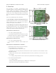
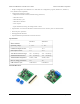
Pololu Jrk USB Motor Controller User's Guide © 2001–2013 Pololu Corporation The jrk 21v3 ships with a 14×1 straight 0.100" male header strip [http://www.pololu.com/catalog/product/965] and two 3.5mm, 2-pin terminal blocks. The jrk 12v12 ships with a 14×1 straight 0.100" male header strip [http://www.pololu.com/catalog/product/965] and two 5mm, 2-pin terminal blocks [http://www.pololu.com/catalog/product/2440]. To provide maximum flexibility, none of these parts are soldered to the board.
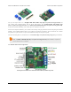
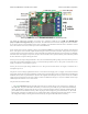
Pololu Jrk USB Motor Controller User's Guide © 2001–2013 Pololu Corporation Pololu jrk 12v12 USB motor controller with feedback, labeled top view. The Pololu jrk USB motor controller can connect to a computer’s USB port via a USB A to mini-B cable [http://www.pololu.com/catalog/product/130] (not included). The USB connection is used to configure the motor controller.
Pololu Jrk USB Motor Controller User's Guide © 2001–2013 Pololu Corporation • The red error LED indicates an error. If there is an error stopping the motor (besides the Awaiting Command error bit), then the red LED will be on. The red LED is tied to the active-high output ERR, so when there is an error, ERR will be driven high, and otherwise it will be pulled low through the LED. • The yellow output status LED indicates the status of the motor.
Pololu Jrk USB Motor Controller User's Guide © 2001–2013 Pololu Corporation Under Linux, the two virtual COM ports created by the jrk should appear as devices with names like /dev/ttyACM0 and /dev/ttyACM1 (the number depends on how many other ACM devices you have plugged in) and you can use any terminal program (such as screen) to send and receive bytes on those ports.
Pololu Jrk USB Motor Controller User's Guide © 2001–2013 Pololu Corporation • The feedback is measured as a value from 0 to 4095. In analog voltage feedback mode, this represents a voltage level of 0 to 5 V. In digital frequency mode, it is a representation of the output speed (see Section 3.c.) The jrk uses this value to compute the scaled feedback, which is a representation of the output of the entire control system.
Pololu Jrk USB Motor Controller User's Guide © 2001–2013 Pololu Corporation 2. Contacting Pololu You can check the Pololu Jrk 21v3 USB Motor Controller page [http://www.pololu.com/catalog/product/1392] or the Pololu Jrk 12v12 USB Motor Controller page [http://www.pololu.com/catalog/product/1393] for additional information. We would be delighted to hear from you about any of your projects and about your experience with the jrk. You can contact us [http://www.pololu.
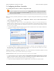
Pololu Jrk USB Motor Controller User's Guide © 2001–2013 Pololu Corporation 3. Configuring the Motor Controller 3.a. Installing Windows Drivers and the Configuration Utility If you use Windows XP, you will need to have Service Pack 3 [http://www.microsoft.com/downloads/ details.aspx?FamilyId=68C48DAD-BC34-40BE-8D85-6BB4F56F5110] installed before installing the drivers for the jrk. See below for details.
Pololu Jrk USB Motor Controller User's Guide © 2001–2013 Pololu Corporation 7. On the second screen of the “Found New Hardware Wizard”, select “Install the software automatically” and click “Next”. 3.
Pololu Jrk USB Motor Controller User's Guide © 2001–2013 Pololu Corporation 8. Windows XP will warn you again that the driver has not been tested by Microsoft and recommend that you stop the installation. Click “Continue Anyway”. 9. When you have finished the “Found New Hardware Wizard”, click “Finish”. After that, another wizard will pop up. You will see a total of three wizards when plugging in the jrk. Follow steps 6-9 for each wizard. 3.
Pololu Jrk USB Motor Controller User's Guide © 2001–2013 Pololu Corporation If you use Windows XP and experience problems installing or using the serial port drivers, the cause of your problems might be a bug in older versions of Microsoft’s usb-to-serial driver usbser.sys. Versions of this driver prior to version 5.1.2600.2930 will not work with the jrk. You can check what version of this driver you have by looking in the “Details” tab of the “Properties” window for usbser.
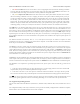
Pololu Jrk USB Motor Controller User's Guide © 2001–2013 Pololu Corporation Windows 8 device manager showing the Pololu Jrk 21v3 Motor Controller Windows XP device manager showing the Pololu Jrk 21v3 Motor Controller Some software will not allow connection to higher COM port numbers. If you need to change the COM port number assigned to your USB device, you can do so using the Device Manager. Bring up the properties dialog for the COM port and click the “Advanced…” button in the “Port Settings” tab.
Pololu Jrk USB Motor Controller User's Guide © 2001–2013 Pololu Corporation 3.b. Input Options The Input tab of the Jrk Configuration Utility The Input tab of the jrk configuration utility contains settings for how the feedback system (consisting of the jrk, a motor and a feedback sensor) is externally controlled and monitored.
Pololu Jrk USB Motor Controller User's Guide © 2001–2013 Pololu Corporation Input scaling The scaling options in this tab determine how the raw input values map to target values, which determine the output of the system. The parameters Maximum and Minimum should be set to the maximum and minimum possible values of the input device; these will be scaled to the target values specified in the right column.
Pololu Jrk USB Motor Controller User's Guide © 2001–2013 Pololu Corporation 3.c. Feedback Options The Feedback tab of the Jrk Configuration Utility The Feedback tab of the jrk configuration utility controls the measurements of the output of the control system. If this section is properly configured, the value of scaled feedback will be 0 when the output is at the minimum position and 4095 when the output is at its maximum.
Pololu Jrk USB Motor Controller User's Guide © 2001–2013 Pololu Corporation the maximum and minimum possible values of the output; these will be converted to scaled feedback values of 4095 and 0, respectively. If the feedback leaves the range specified by the Absolute Max and Absolute Min parameters, a Feedback disconnect error will occur. For convenience, the Invert feedback direction option is provided.
Pololu Jrk USB Motor Controller User's Guide © 2001–2013 Pololu Corporation duty cycle target =(Proportional coefficient) × error + (Integral coefficient) × integral + (Derivative coefficient) × derivative The integral is computed as the sum of the error over all PID cycles, and the derivative is the current error minus the previous error. The error itself is the difference of the scaled feedback and the target (error = scaled feedback – target).
Pololu Jrk USB Motor Controller User's Guide © 2001–2013 Pololu Corporation 3.e. Motor Options The Motor tab of the Jrk Configuration Utility The Motor tab of the jrk configuration utility controls the PWM [http://en.wikipedia.org/wiki/Pulse-width_modulation] signal applied to the motor, including all limits that are applied when converting duty cycle target to duty cycle. The jrk’s PWM duty cycle has a range of -600 to 600, where -600 is full reverse and 600 is full forward.
Pololu Jrk USB Motor Controller User's Guide © 2001–2013 Pololu Corporation However, a higher PWM frequency means greater power loss due to switching, which could make a 5 kHz PWM frequency a better choice for certain applications. Additionally, the 5 kHz PWM frequency allows for finer control at duty cycles approaching 0% or 100% (±600). This is because the timing characteristics of the jrk motor drivers make it so that very short PWM pulses (either low or high) have no effect on the output voltage.
Pololu Jrk USB Motor Controller User's Guide © 2001–2013 Pololu Corporation As of firmware version 1.4, the behavior of the jrk 12v12 when the duty cycle is zero depends on the “When motor is off” configuration option. In previous versions, at a duty cycle of 0, the jrk 12v12 would brake the motor in one direction but let it coast in the other direction. 3.f. Error Response Options The Errors tab of the Jrk Configuration Utility There are several errors that can stop the jrk from driving its motor.
Pololu Jrk USB Motor Controller User's Guide © 2001–2013 Pololu Corporation 3.g. The Plots Window The Plots window of the configuration utility displays real-time data from the jrk, scrolling from right to left. To access this window, select “Plots” from the Window menu, or click on the small plot displayed in the upper-right corner of the main window. All of the variables discussed in Section 1.c are available. Each variable can be independently scaled to a useful range.
Pololu Jrk USB Motor Controller User's Guide © 2001–2013 Pololu Corporation You can determine the version of your jrk’s firmware by running the configuration utility (Section 3.a), connecting to a jrk, and looking at the firmware version number which is displayed in the upper left corner below the “Connected to” dropdown box. Version 1.4 of the firmware for the jrk 12v12 extends the “When motor is off” parameter so that it now affects the behavior of the jrk whenever the duty cycle is 0.
Pololu Jrk USB Motor Controller User's Guide © 2001–2013 Pololu Corporation 10. It will take a few seconds to erase the jrk’s existing firmware and load the new firmware. Do not disconnect the jrk during the upgrade. 11. Once the upgrade is complete, the Firmware Upgrade window will close, the jrk will disconnect from your computer once again, and it will reappear as it was before. If there is only one Jrk plugged in to your computer, the Pololu Jrk Configuration Utility will connect to it.
Pololu Jrk USB Motor Controller User's Guide © 2001–2013 Pololu Corporation 4. Using the Serial Interface 4.a. Serial Modes The jrk has three different serial interfaces. First, it has the RX and TX lines. The jrk can send bytes on the TX line. If the jrk is in serial input mode, the RX line can be used to receive non-inverted, TTL (0 – 5 V) serial bytes (Section 4.b).
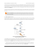
Pololu Jrk USB Motor Controller User's Guide © 2001–2013 Pololu Corporation UART The UART serial mode. In this mode, the TX and RX lines can be used to send commands to the jrk and receive responses from it. Any byte received on RX will be sent to the Command Port, but bytes sent from the Command Port will be ignored. The TTL Port is not used. The baud rate on TX and RX can either be automatically detected by the jrk when a 0xAA byte is received on RX, or it can be set to a fixed value ahead of time.
Pololu Jrk USB Motor Controller User's Guide © 2001–2013 Pololu Corporation start bit, 8 data bits, and a stop bit, each byte takes 10 bit times to transmit, so the fastest possible data rate in bytes per second is the baud rate divided by ten. At the jrk’s maximum baud rate of 115,200 bits per second, the maximum realizable data rate, with a start bit coming immediately after the preceding byte’s stop bit, is 11,520 bytes per second.
Pololu Jrk USB Motor Controller User's Guide © 2001–2013 Pololu Corporation jrk on the line whose device number matches the specified device number accepts the command that follows; all other Pololu devices ignore the command. The remaining bytes in the command packet are the same as the compact protocol command packet you would send, with one key difference: the compact protocol command byte is now a data byte for the command 0xAA and hence must have its most significant bit cleared.
Pololu Jrk USB Motor Controller User's Guide © 2001–2013 Pololu Corporation 2. Add 7 zeros to the end of your message. 3. Write your CRC-7 polynomial underneath the message so that the LSB of your polynomial is directly below the LSB of your message. 4. If the LSB of your CRC-7 is aligned under a 1, XOR the CRC-7 with the message to get a new message; if the LSB of your CRC-7 is aligned under a 0, do nothing. 5. Shift your CRC-7 right one bit.
Pololu Jrk USB Motor Controller User's Guide © 2001–2013 Pololu Corporation This command will turn the motor off by setting the Awaiting Command error bit. The jrk will not restart the motor until it receives a Set Target command. The jrk can be configured to either brake or coast while the motor is off (Section 3.e).
Pololu Jrk USB Motor Controller User's Guide © 2001–2013 Pololu Corporation Set Target Low Resolution Reverse Compact protocol: 0xE0, magnitude Pololu protocol: 0xAA, device number, 0x60, magnitude If magnitude is zero, then this command is equivalent to the Motor Off command above: the Awaiting Command error bit will be set, so the jrk will turn the motor off until another Set Target command is received.
Pololu Jrk USB Motor Controller User's Guide © 2001–2013 Pololu Corporation input value. The jrk can recover from the error by receiving four good pulses in a row. This error does not occur in Analog Input Mode or Serial Input Mode. • Bit 4: Input disconnect This error occurs when the input is above the Absolute maximum or below the Absolute minimum (these parameters can be set in the configuration utility).
Pololu Jrk USB Motor Controller User's Guide © 2001–2013 Pololu Corporation This command is equivalent to reading the “Currently stopping motor?” column in the Errors tab of the configuration utility, and then clicking the “Clear Errors” button. If an error is stopping the motor (besides the Awaiting Command error bit), the jrk will turn the red LED on and drive the ERR line high, and this command can be used to determine the cause of the error.
Pololu Jrk USB Motor Controller User's Guide © 2001–2013 Pololu Corporation Read Variable Command Byte Variable Range Two bytes Low byte High byte Input 0 to 4095 0xA1 0x81 0x82 Target 0 to 4095 0xA3 0x83 0x84 Feedback 0 to 4095 0xA5 0x85 0x86 Scaled feedback 0 to 4095 0xA7 0x87 0x88 Error sum (integral) -32,768 to 32,767 0xA9 0x89 0x8A Duty cycle target -32,768 to 32,767 0xAB 0x8B 0x8C Duty cycle -600 to 600 0x8D 0x8E Current 0 to 255 PID period count 0 to 65535 0xAD
Pololu Jrk USB Motor Controller User's Guide © 2001–2013 Pololu Corporation different from the duty cycle target because it takes in to account all of the jrk’s configurable limits: maximum acceleration, maximum duty cycle, maximum current, and also brake duration (Section 3.e). • PID period count: This is the number of PID periods that have elapsed. It resets to 0 after reaching 65535. The duration of the PID period can be configured (Section 3.d).
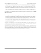
Pololu Jrk USB Motor Controller User's Guide © 2001–2013 Pololu Corporation Connections Connect the TX line of the master device to the RX lines of all of the slave devices. Commands sent by the master will then be received by all slaves. Receiving serial responses from one the slave devices on the PC can be achieved by connecting the TX line of that slave device to the RX line of the jrk. Receiving serial responses from multiple slave devices is more complicated.
Pololu Jrk USB Motor Controller User's Guide © 2001–2013 Pololu Corporation #include #include #include #ifdef _WIN32 #define O_NOCTTY 0 #else #include #endif // Reads a variable from the jrk. // The 'command' argument must be one of the two-byte variable-reading // commands documented in the "Variable Reading Commands" section of // the jrk user's guide.
Pololu Jrk USB Motor Controller User's Guide © 2001–2013 Pololu Corporation int feedback = jrkGetFeedback(fd); printf("Current Feedback is %d.\n", feedback); int target = jrkGetTarget(fd); printf("Current Target is %d.\n", target); int newTarget = (target < 2048) ? 3000 : 1000; printf("Setting Target to %d.\n", newTarget); jrkSetTarget(fd, newTarget); } close(fd); return 0; 4.i.2.
Pololu Jrk USB Motor Controller User's Guide © 2001–2013 Pololu Corporation 5. Setting Up Your System The following step-by-step procedure is recommended for configuring a feedback system for use with a jrk motor controller. Connecting power and feedback 1. Connect your jrk to a PC with a USB cable and launch the configuration utility. The red LED should be on. 2. Select the “Reset to default settings…” option from the File menu to load a safe set of settings. 3.
Pololu Jrk USB Motor Controller User's Guide © 2001–2013 Pololu Corporation 1. Turn off power. 2. Connect your motor wires to the jrk’s A and B motor outputs. If possible, connect them so that positive voltage at A causes the motor to drive forward. 3. Turn on power. Testing the motor 1. If possible, drive your motor with feedback disabled. To do this, make sure that the Feedback mode is set to none and use the controls on the Input tab to apply different duty cycles.
Pololu Jrk USB Motor Controller User's Guide © 2001–2013 Pololu Corporation 4. Note how close your system gets to an error of zero using just the proportional term. You can use the integral term to get it much lower: with the integral limit set at 1000, try increasing the Integral Coefficient until you see a correction that brings the error closer to zero.
Pololu Jrk USB Motor Controller User's Guide 5.
Pololu Jrk USB Motor Controller User's Guide © 2001–2013 Pololu Corporation 6. Writing PC Software to Control the Jrk There are two ways to write PC software to control the jrk: the native USB interface and the virtual serial port. The native USB interface provides more features than the serial port, such as the ability to change configuration parameters and select the jrk by its serial number. Also, the USB interface allows you to recover more easily from temporary disconnections.