
Manual

3.c. Feedback Options
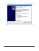
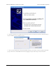
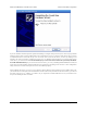
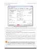
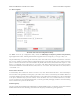
The Feedback tab of the Jrk Configuration Utility
The Feedback tab of the jrk configuration utility controls the measurements of the output of the control system. If
this section is properly configured, the value of scaled feedback will be 0 when the output is at the minimum position
and 4095 when the output is at its maximum. There are three available feedback modes:
• None indicates that feedback and the PID calculation are disabled. In this mode, the duty cycle target is equal
to target − 2048 instead of being the result of a PID calculation. This means that a target of 2648 will correspond
to driving the motor full speed forward, 2048 is brake, and so on. However, the jrk still performs all of its
calculations once per “PID period”.
• Analog voltage is used when an analog voltage source, such as a potentiometer, connected to the FB pin
indicates the position of the output. A signal level of 0 V corresponds to a feedback value of 0, and a signal level
of 5 V corresponds to a feedback value of 4092.
• Frequency (digital) is used with speed-measuring devices that generate pulses at a rate proportional to the
speed of the output shaft, such as a tachometer. A simple example is an optical breakbeam sensor measuring
the rotation of a slotted disk. The number of pulses detected on the FB pin during each PID period is used as
a measurement of speed. When driving the motor forward (i.e. target > 2048), the feedback value is 2048+n,
where n is the number of pulses, and when driving the motor in reverse, the feedback value is 2048-n. Since
the feedback value must be between 0 and 4095, the jrk can measure at most 2047 pulses per PID period. This
allows for a maximum frequency of approximately 2 MHz with a PID period of 1 ms.
Feedback scaling
The scaling options in this tab determine how the raw feedback values map to scaled feedback values, which are
intended to be a representation of the output of the system. The parameters Maximum and Minimum should be set to
Pololu Jrk USB Motor Controller User's Guide © 2001–2013 Pololu Corporation
3. Configuring the Motor Controller Page 17 of 44