
Manual


• The feedback is measured as a value from 0 to 4095. In analog voltage feedback mode, this represents a
voltage level of 0 to 5 V. In digital frequency mode, it is a representation of the output speed (see Section 3.c.)
The jrk uses this value to compute the scaled feedback, which is a representation of the output of the entire
control system. A scaled feedback of 0 should represent the minimum position of the system, and 4095 should
represent the maximum position.
• The current through the motor is measured as a number from 0 to 255. A calibration value relates this to an
actual current in amps.
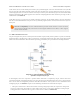
Every PID cycle, the jrk performs the following computations to determine the behavior of the motor (see Section
3.d for more information):
1. The error is computed as the difference of scaled feedback and target (error = scaled feedback − target).
2. An implementation of the PID algorithm is applied to the error. PID stands for the three terms that are added
together: proportional (proportional to the error), integral (proportional to the accumulated sum of the error over
time), and derivative (proportional to the difference of the error relative to the previous PID period.) The three
constants of proportionality are the most important parameters determining the behavior of the control system.
The result of the PID algorithm is a number from -600 to +600 called the duty cycle target.
3. The duty cycle target is reduced according to various configurable limits, including acceleration, current, and
maximum duty cycle limits (Section 3.e). The limits are intended to prevent the system from causing damage to
itself under most circumstances.
The resulting value becomes the duty cycle of the PWM (pulse width modulation) signal applied to the motor. A value
of +600 corresponds to 100% duty cycle in the forward direction, a value of -600 corresponds to 100% duty cycle in
the reverse direction, and a value of 0 corresponds to 0% duty cycle or off.
Various parameters and commands have an effect on the steps described above. For example, feedback may be turned
off so that the jrk can become a simple speed controller; in this case the PID calculation is bypassed and the duty
cycle target is just equal to the target minus 2048. In this mode, limits applied to the duty cycle continue to provide a
useful way of preventing damage to the system. As another example, a command to turn the system off prevents the
motors from being driven, but all measurements and calculations continue to occur normally.
Pololu Jrk USB Motor Controller User's Guide © 2001–2013 Pololu Corporation
1. Overview Page 8 of 44