Pololu Orangutan USB Programmer User's Guide © 2001–2011 Pololu Corporation Pololu Orangutan USB Programmer User's Guide 1. Overview . . . . . . . . . . . . . . . . . . . . . . . . . 2. Contacting Pololu . . . . . . . . . . . . . . . . . . . . . 3. Module Pinout and Components . . . . . . . . . . . . . 4. USB-to-Serial Drivers . . . . . . . . . . . . . . . . . . 5. Getting Started Using Windows . . . . . . . . . . . . . 5.a. Using AVR Studio 4 . . . . . . . . . . . . . . . . 5.b.
Pololu Orangutan USB Programmer User's Guide © 2001–2011 Pololu Corporation 1. Overview The Orangutan USB Programmer [http://www.pololu.com/catalog/product/740] is a compact solution for programming our Orangutan robot controllers [http://www.pololu.com/catalog/category/8] or 3pi robot [http://www.pololu.com/catalog/product/975] through a USB port.
Pololu Orangutan USB Programmer User's Guide © 2001–2011 Pololu Corporation 2. Contacting Pololu You can check the Orangutan USB Programmer page [http://www.pololu.com/catalog/product/740] for additional information. We would be delighted to hear from you about any of your projects and about your experience with the Orangutan USB programmer. You can contact us [http://www.pololu.com/contact] directly or post on our forum [http://forum.pololu.com/].
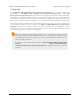
Pololu Orangutan USB Programmer User's Guide © 2001–2011 Pololu Corporation 3. Module Pinout and Components Pololu Orangutan USB Programmer labeled top view USB-to-Serial Adapter Mode: The location of the blue mode jumper determines whether the device will function as a programmer or a USB-toserial adapter.
Pololu Orangutan USB Programmer User's Guide © 2001–2011 Pololu Corporation If you have programmer version PGM02B, you will have additional LED feedback. Every time your programmer powers up (i.e. when you connect it to your computer), the red and green status LEDs will both light for five seconds. During this period, the programmer is receptive to firmware updates; you should avoid trying to program until the initial five seconds have elapsed and the two status LEDs have turned off.
Pololu Orangutan USB Programmer User's Guide © 2001–2011 Pololu Corporation header pin 1. Unlike the Orangutan, the Baby Orangutan does not come with a shrouded header to enforce correct cable orientation; the red wire and arrow mark on the cable’s ISP connector should be lined up with the arrow to pin 1 on the Baby Orangutan PCB.
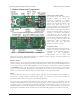
Pololu Orangutan USB Programmer User's Guide © 2001–2011 Pololu Corporation 4. USB-to-Serial Drivers Before you connect your Orangutan USB programmer to your computer, you must install the driver [http://www.pololu.com/docs/0J7/] for the programmer’s CP2102 USB-to-UART bridge. Once you have successfully installed your this driver, you should see the green USB status LED near the mini-B connector lit whenever it is connected to your computer. 4.
Pololu Orangutan USB Programmer User's Guide © 2001–2011 Pololu Corporation 5. Getting Started Using Windows After you’ve installed the necessary drivers, the next step is to download and install a compiler. WinAVR, located at http://winavr.sourceforge.net/ [http://winavr.sourceforge.net/], is an open source suite of software development tools for the Atmel AVR series of microcontrollers. It includes the GNU GCC compiler for C and C++. Follow the installation instructions they provide.
Pololu Orangutan USB Programmer User's Guide © 2001–2011 Pololu Corporation Creating a new AVR Studio project, step 1 2. Select AVR Simulator as the debug platform and then select the appropriate device for your Orangutan or 3pi. This will either be ATmega48, ATmega168, or ATmega328P depending on which chip your Orangutan or 3pi has. Click Finish. Creating a new AVR Studio project, step 2 3. Write your program in BlinkLED.
Pololu Orangutan USB Programmer User's Guide © 2001–2011 Pololu Corporation Building a project with AVR Studio Note: You will probably want to customize this program slightly if you are working with an original Orangutan rather than a Baby Orangutan, Orangutan SV-168, Orangutan SV-328, Orangutan LV-168, or 3pi robot. F_CPU should be defined as the clock frequency of your target device in Hz.
Pololu Orangutan USB Programmer User's Guide © 2001–2011 Pololu Corporation ports until it detects the programmer. You can determine your programmer’s serial port by looking in the “Ports (COM & LPT)” list of your Device Manager for “Pololu USB-to-serial adapter”. Click “Connect…” to bring up the AVRISP dialog. You should see the green programming status LED flash very briefly as the dialog appears.
Pololu Orangutan USB Programmer User's Guide © 2001–2011 Pololu Corporation navigate to your project’s folder, you should find it as “default\.hex”. Click the Program button (make sure you click the one in the Flash section, not one in the “EEPROM” or “ELF Production File Format” sections!).
Pololu Orangutan USB Programmer User's Guide © 2001–2011 Pololu Corporation If there were no problems, the red LED on your Orangutan, Baby Orangutan, or 3pi should now be flashing! Note that if you are trying this on a 3pi robot and you haven’t yet soldered in the optional through-hole LEDs, you will need to turn your 3pi robot over to see the flashing LED as the surface-mounted LEDs are located on the underside of the 3pi’s PCB.
Pololu Orangutan USB Programmer User's Guide © 2001–2011 Pololu Corporation Listed Frequency Actual Frequency Allowed Target Frequency 1.845 MHz 2.5 MHz > 10 MHz 460.8 kHz 1.25 MHz > 5 MHz 115.2 kHz 625 kHz > 2.5 MHz 57.6 kHz 156 kHz > 625 kHz 4.00 kHz 3.91 kHz > 16 kHz 1.21 kHz* 610 Hz* > 2.5 kHz* * This ISP frequency is so low that AVR Studio times out when it tries to program flash or EEPROM, but it can be used to program fuses and lock bits.
Pololu Orangutan USB Programmer User's Guide © 2001–2011 Pololu Corporation • Auto This tab lets you automatically perform a scripted set of programming actions. If you are going to be configuring many devices the same way, it might be convenient for you to do this using the Auto tab features. 5.c. Configuring Your Programmer for AVR Studio 4 Configuring your programmer’s version numbers is purely optional. Your programmer will still function with incorrect or mismatched version numbers.
Pololu Orangutan USB Programmer User's Guide © 2001–2011 Pololu Corporation here we have transmitted: config Once the versions are transmitted, the programmer waits for a configuration command. The two valid commands are “s”, for software version configuration, and “h”, for hardware version configuration. The screen shots below show us configuring our programmer’s software version to be 2.0A, which will match what our AVR Studio expects. here we have transmitted: s here we have transmitted: 2.
Pololu Orangutan USB Programmer User's Guide © 2001–2011 Pololu Corporation cd C:\BlinkLED\default avrdude -p m168 -P COM2 -c avrispv2 -e -U flash:w:BlinkLED.hex The argument following the -p is the part number and should be m328p, m168, or m48. The argument following the -P is the port; you can use your computer’s Device Manager to figure out the COM port of your Orangutan USB programmer. The programmer ID is specified using the -c option and should be avrispv2.
Pololu Orangutan USB Programmer User's Guide © 2001–2011 Pololu Corporation 6. Getting Started Using Linux Recent versions of the linux kernel include support for the Pololu Orangutan USB Programmer as part of the usbserial driver. We have tested the following instructions under Ubuntu Linux 7.04; if you experience any problems, we recommend you upgrade to the most recent version of your distribution.
Pololu Orangutan USB Programmer User's Guide © 2001–2011 Pololu Corporation Reading | ################################################## | 100% 0.02s avrdude: Device signature = 0x1e9406 avrdude: NOTE: FLASH memory has been specified, an erase cycle will be performed To disable this feature, specify the -D option. avrdude: erasing chip avrdude: reading input file "BlinkLED.hex" avrdude: input file BlinkLED.
Pololu Orangutan USB Programmer User's Guide © 2001–2011 Pololu Corporation 7. Troubleshooting If Your Computer Fails to Connect to the Programmer • Make sure your programmer is connected to your computer via a USB A to mini-B cable. If it was previously working and has since stopped, try cycling the power by unplugging it from your computer and then reconnecting it. • Make sure you have installed the drivers the Orangutan USB programmer needs to operate.
Pololu Orangutan USB Programmer User's Guide © 2001–2011 Pololu Corporation trace somewhere on your target device. The ideal way to test for this would be to try programming a different device with your Orangutan USB programmer (or, conversely, try using a different programmer to program your target device). If this is not an option, try verifying that your target device is still functional and perform some continuity tests to check for shorts or disconnections on the ISP programming lines.
Pololu Orangutan USB Programmer User's Guide © 2001–2011 Pololu Corporation 8. Updating Your Programmer's Firmware Note: Only programmer revision PGM02B supports firmware upgrades. If you have revision PGM02A, this section does not apply to your product. On August 20, 2008 we released a firmware update (firmware version 1.4) for the Orangutan USB programmer revision PGM02B that fixes a bug where the programmer could be left trying to drive some of its programming lines high if programming failed.
Pololu Orangutan USB Programmer User's Guide © 2001–2011 Pololu Corporation 1. Install a suitable terminal program To perform the firmware update, you will need a terminal program capable of sending binary files. We recommend Tera Term Pro v2.3, available for free at http://hp.vector.co.jp/authors/VA002416/teraterm.html [http://hp.vector.co.jp/authors/VA002416/teraterm.html]. Installation instructions are included in the downloaded .zip file. 8.
Pololu Orangutan USB Programmer User's Guide © 2001–2011 Pololu Corporation 2. Close any programmer serial port connections Close any existing COM port connections you have that might interfere with the upgrading process. For example, if you have AVR Studio open, make sure the AVRISP programming window is closed as this window ties up the COM port your programmer is using. 8.
Pololu Orangutan USB Programmer User's Guide © 2001–2011 Pololu Corporation 3. Determine your COM port Using the Windows device manager to identify the programmer’s COM port Connect your programmer to your computer and bring up your computer’s device manager. One way to accomplish this is through the hardware tab of the System control panel. Another way is to right-click on “My Computer” and select “manage,” which should bring up a window like the one shown above.
Pololu Orangutan USB Programmer User's Guide © 2001–2011 Pololu Corporation 4. Make sure your port is COM1 through COM4 (TeraTerm only) Tera Term cannot connect to COM6, so we need to change the COM port number. Right-click the “Pololu USBto-serial adapter (COMx)” and select “Properties”. Select the “Port Settings” tab of the resulting dialog box and click the “Advanced…” button. At the bottom of the next dialog box is a drop-down list labeled “COM Port Number”.
Pololu Orangutan USB Programmer User's Guide © 2001–2011 Pololu Corporation If COM1 through COM4 are all in use, you have three options: 1) find a way to free up one of those ports by disconnecting something 2) find another terminal program that will let you send binary files to ports greater than COM4 3) reassign your programmer to an “in use” port that you know nothing is currently connected to.
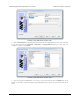
Pololu Orangutan USB Programmer User's Guide © 2001–2011 Pololu Corporation 1. Run Tera Term Pro v2.3 You will be greeted by a “TeraTerm: New connection” dialog box. Click cancel, then go to the “Setup” menu and select “Serial port…”. Configure the settings as shown below, substituting your own COM port. The baud rate should be 115200 with 8-bit data, no parity, one stop bit, and no flow control. You do not need any transmit delays.
Pololu Orangutan USB Programmer User's Guide 8.
Pololu Orangutan USB Programmer User's Guide © 2001–2011 Pololu Corporation 2. Enter the programmer’s firmware update mode When you connect your programmer to your computer via the USB cable, you should see both the red and green status LEDs light for approximately five seconds. During this time, the programmer is waiting for the proper input sequence that will put it into firmware update mode.
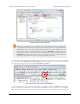
Pololu Orangutan USB Programmer User's Guide © 2001–2011 Pololu Corporation 3. Loading the new firmware From the “File” menu, select “Send file….” Navigate to the directory that has the .pgm file you wish to upload and select the file. Before you click “Open,” make sure you have checked the binary checkbox option in the lower left part of the window. If you fail to check this box, the upload will fail. 8.
Pololu Orangutan USB Programmer User's Guide © 2001–2011 Pololu Corporation When you click “Open”, you should see periods streaming across your terminal window . Each period represents the successful transmission of a packet. You should also see the red status LED below the reset button flickering as the firmware update progresses. When the upload is complete, the programmer will transmit *SUCCESS to indicate success.