Orangutan X2 Command Documentation v1.01 © 2001–2010 Pololu Corporation Orangutan X2 Command Documentation v1.
Orangutan X2 Command Documentation v1.01 © 2001–2010 Pololu Corporation 1. Overview . . . . . . . . . . . . . . . . . . . . . . . . . . . . . . . . . . . . . . . . . . . . . . 2. ATmega644 SPI Configuration . . . . . . . . . . . . . . . . . . . . . . . . . . . . . . . . . . 3. Low-Level SPI Commands . . . . . . . . . . . . . . . . . . . . . . . . . . . . . . . . . . . . . 3.a. Motor Commands . . . . . . . . . . . . . . . . . . . . . . . . . . . . . . . . . . . . . . 3.a.01. Command 214: Set Motor Mode . .
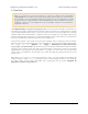
Orangutan X2 Command Documentation v1.01 © 2001–2010 Pololu Corporation 1. Overview Note: As of October 25, 2010, all Orangutan X2 versions are shipping with programmable ATmega1284P microcontrollers instead of the ATmega644P included on older units, and the auxiliary microcontroller is now an ATmega328P instead of an ATmega168. The ATmega1284P has 128 KB of program memory, 16 KB of RAM, and 4 KB of EEPROM, and it offers an additional 16-bit timer (TIMER3).
Orangutan X2 Command Documentation v1.01 © 2001–2010 Pololu Corporation 2. ATmega644 SPI Configuration The mega644 SPI module should be configured as follows: • SPI enabled • MSB first • master mode • clock polarity 0 (clock line low when idle) • clock phase 0 (sample on leading ege) • Maximum frequency: 2.5 MHz (clock/8) If you have the latest WinAVR [http://winavr.sourceforge.
Orangutan X2 Command Documentation v1.01 { } © 2001–2010 Pololu Corporation __asm__ volatile ( "1: push r22" "\n\t" " ldi r22, 4" "\n\t" "2: dec r22" "\n\t" " brne 2b" "\n\t" " pop r22" "\n\t" " sbiw %0, 1" "\n\t" " brne 1b" : "=w" ( microseconds ) : "0" ( microseconds ) ); unsigned char SPIReceive( unsigned char data ) // data is often a junk byte (e.g.
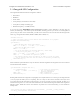
Orangutan X2 Command Documentation v1.01 © 2001–2010 Pololu Corporation 3. Low-Level SPI Commands We will now elaborate on the low-level SPI commands. Some commands produce immediate results (e.g. non-acceleration motor commands, all the read commands, buzzer off) independent of the state of the mega168’s main loop. Others queue up actions to be carried out by the appropriate handler in the mega168’s main loop (e.g. UART transmit, most buzzer commands, acceleration motor commands).
Orangutan X2 Command Documentation v1.01 © 2001–2010 Pololu Corporation If you want to run your X2 in joint motor mode, you should connect one terminal of your motor to the two M1 outputs and the other terminal of your motor to the two M2 outputs. It is important to note that current sensing is not possible in joint motor mode. The Set Current Limits command (192—Section 3.a.10) will have no effect in joint motor mode and the Get Average Motor Current command (216—Section 3.a.
Orangutan X2 Command Documentation v1.01 © 2001–2010 Pololu Corporation 3.a.05. Command 144: Joint Motor Operation (inA1 = inB1 = in1; inA2 = inB2 = in2) Effect: Use dual motor drivers together as a single, more powerful motor driver. The settings of in1 and in2 determine if the effect is brake low, forward, or reverse at thedesired PWM. This command sets motor to the specified state immediately. It is not possible to brake high in joint motor mode.
Orangutan X2 Command Documentation v1.01 © 2001–2010 Pololu Corporation command byte = 208 | motor bit data byte = 7-bit acceleration (MSB always zero) 3.a.08. Command 188: Set Brake Duration Effect: Sets the duration the specified motor spends braking low at 100% duty cycle when issued an acceleration command (228—Section 3.a.06 or 232—Section 3.a.04) that results in a change of direction.
Orangutan X2 Command Documentation v1.01 © 2001–2010 Pololu Corporation 3.a.10. Command 192: Set Current Limit Effect: Sets the current limit for the specified motor and the current control constant P (proportional component of PID). The current limit is provided as an 8-bit value that is continuously compared to the corresponding motor current average measured using the ADC. The control constant P is a 7-bit value that determines how the motor behaves in the vicinity of the current limit.
Orangutan X2 Command Documentation v1.01 © 2001–2010 Pololu Corporation losses, however the motor 1 PWM frequency is used for acceleration timing, so decreasing it below 1 kHz can slightly reduce the frequency at which acceleration updates are performed (at the lowest frequency, acceleration updates will occur every 13 ms instead of every 10 ms).The frequencies can be different for each motor so long as the X2 isn’t being run in joint motor mode.
Orangutan X2 Command Documentation v1.01 © 2001–2010 Pololu Corporation 3.b.1. Command 152: Play Note Effect: Plays the desired note immediately, where note is an 8-bit encoding of the frequencies of the equaltempered scale centered around A4 = 440 Hz. Note 0xFF is defined to be a “silent note,” which merely silences the buzzer for a desired period of time. Notes that produce frequencies less than 40 Hz or greater than 10 kHz are not allowed and will result in the closest note that is allowed.
Orangutan X2 Command Documentation v1.01 © 2001–2010 Pololu Corporation data byte 2 = most significant byte of duration word (minus the MSB, which is in the command byte) data byte 3 = least significant byte of duration word (minus the MSB, which is in the command byte) 3.b.2. Command 160: Play Frequency Effect: Plays the desired frequency immediately. Allowed frequencies are those greater than 40 Hz and less than 10 kHz. The frequency is a 15-bit value specified in Hz.
Orangutan X2 Command Documentation v1.01 © 2001–2010 Pololu Corporation 3.b.4. Command 168: Store Note Effect: This command is used to store a sequence of notes in the mega168’s EEPROM that can then be played as a melody. Each stored note consists of an 8-bit note-frequency enumeration byte and a 16-bit millisecondduration word. For details on note enumeration, see the Play Note command (152—Section 3.b.1).
Orangutan X2 Command Documentation v1.01 © 2001–2010 Pololu Corporation command byte = 186 3.b.7. Command 226: Set Volume Effect: Sets the buzzer volume by affecting the duty cycle of the PWM sent to the buzzer. The formula used is duty cycle = TOP >> (16 – volume), where 0 <= volume <= 15. A max volume of 15 produces a 50% duty cycle.
Orangutan X2 Command Documentation v1.01 © 2001–2010 Pololu Corporation in normal mode: baud = ( 20 MHz / 16 ) / ( UBRR + 1 ) = 1.25 MHz / ( UBRR + 1 ), so UBRR = ( 1.25 MHz / baud ) – 1 in double-speed mode: baud = ( 20 MHz / 8 ) / ( UBRR + 1 ) = 2.5 MHz / ( UBRR + 1 ), so UBRR = ( 2.5 MHz / baud ) – 1 Note: If you are using firmware version 1.00, you must give the mega168 time to set its serial parameters to the desired values before issuing a serial-transmit command.
Orangutan X2 Command Documentation v1.01 © 2001–2010 Pololu Corporation data byte 1 = (permanent program mode bit << 6) | (stop-bits bit << 5) | (2x-speed bit << 4) | (UBRRH << 1) | MSB of UBRRL data byte 2 = seven lowest bits of UBRRL If you want to enable permanent programming mode, you only need to send: command byte = 200 data byte 1 = 64 data byte 2 = 0 3.c.02.
Orangutan X2 Command Documentation v1.01 © 2001–2010 Pololu Corporation Values sent: UART byte (8 bits) command byte = 220 | MSB of send byte data byte = seven lowest bits of send byte 3.c.04. Command 222: Get Free Space in Send Buffer Effect: This command loads into the mega168’s SPDR (SPI data register) the number of unoccupied bytes in the UART send buffer. Sending a second byte (either the NULL command or a junk data byte) over the SPI once the value is loaded will transfer it to the mega644’s SPDR.
Orangutan X2 Command Documentation v1.01 © 2001–2010 Pololu Corporation 3.c.07. Command 252: Get UART Error Effect: This command loads into the mega168’s SPDR (SPI data register) the UART error byte, which reflects any UART errors that have occured. Sending a second byte (either the NULL command or a junk data byte) over the SPI once the value is loaded will transfer it to the mega644’s SPDR.
Orangutan X2 Command Documentation v1.01 © 2001–2010 Pololu Corporation • bit 3: STATUS_BUZZER_FINISHED — the buzzer has finished playing and is now silent. This bit reflects the real-time state of the buzzer and is not cleared by reading the status byte. • bit 4: STATUS_M1_FAULT — a fault has occurred with motor 1. This bit is latched and will remain set until the status byte is read. • bit 5: STATUS_M1_CURRENT_HIGH — the average motor 1 current has met or exceeded the specified current limit.
Orangutan X2 Command Documentation v1.01 © 2001–2010 Pololu Corporation 3.d.03. Command 248: Read from EEPROM Effect: This command will read a byte from the specified address of the mega168’s EEPROM and return it to the mega644 using the SPDR. The EEPROM is addressed by a 9-bit value (512 bytes of memory). When processing the command byte, the SPI interrupt routine will check to see if it’s currently possible to read from the EEPROM.
Orangutan X2 Command Documentation v1.01 © 2001–2010 Pololu Corporation 7. read SPDR to obtain the minor version byte Values sent: none command byte = 253 data byte = any seven-bit value 3.d.06. Command 255: NULL Command Effect: No action is taken Values sent: none command byte = 255 3.
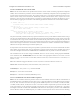
Orangutan X2 Command Documentation v1.01 © 2001–2010 Pololu Corporation 4. Attention and SPI Pins Orangutan X2 SPI and attention pins 4.a. ATmega168's Attention Line Whenever a bit gets set in the mega168’s status byte, the mega168 sets its attention line. Whenever a Get Status command (218—Section 3.d.01) is issued, the mega168 clears the attention line.
Orangutan X2 Command Documentation v1.01 © 2001–2010 Pololu Corporation (2×3) holes next to the Slave Select hole contain the SPI MISO (Master In, Slave Out), MOSI (Master Out, Slave In), and SCK (SPI Clock) lines. If you want to connect any additional slave devices, you will need to use these lines. Please see the Orangutan X2 schematic [http://www.pololu.com/file/download/ox2_schematic.
Orangutan X2 Command Documentation v1.01 © 2001–2010 Pololu Corporation 5. ATmega168's EEPROM Addresses This section details the mega168 settings that can be saved to EEPROM, the format of those settings, and the addresses to which they should be written. When writing to EEPROM, remember that an EEPROM memory address can be written thousands of times, but not infinitely many.
Orangutan X2 Command Documentation v1.
Orangutan X2 Command Documentation v1.01 © 2001–2010 Pololu Corporation 20: ADDR_SCK_DURATION — programmer SPI SCK setting (0 is fastest). This determines how quickly you can upload a hex file from the mega168 to the mega644 while programming. This parameter can be changed setting the ISP frequency in Main tab of AVR Studio’s AVRISP dialog window. Default value is 0. 21: ADDR_ISP_STATE — mega168 ISP state (in progmode or not).