
Manual

6. Cyclic Redundancy Check (CRC) Error Detection
For certain applications, verifying the integrity of the data you’re sending and receiving can be very important.
Because of this, the qik has optional 7-bit cyclic redundancy checking, which is similar to a checksum but more
robust as it can detect some possible errors, such as an extra zero byte, that would not affect a checksum.
When jumper B is in place, cyclic redundancy checking is enabled. In CRC mode, the qik expects an extra byte
to be added onto the end of every command packet. The lower seven bits of this byte must be the 7-bit CRC for
that packet, or else the qik will set its CRC Error bit in the error byte and ignore the command. The qik does not
append any CRC information to the data it sends back, which always consists of just one byte.
A detailed account of how cyclic redundancy checking works is beyond the scope of this document, but you can
find a wealth of information using Wikipedia [http://en.wikipedia.org/wiki/Cyclic_redundancy_check]. The quick version
is that a CRC computation is basically a carryless long division of a CRC “polynomial” 0x91 into your message
(expressed as a continuous stream of bits), where all you care about is the remainder. The qik uses CRC-7,
which means it uses an 8-bit polynomial (whose most-significant bit, or MSB, must always be 1) and, as a result,
produces a 7-bit remainder. This remainder is the lower 7 bits of the CRC byte you tack onto the end of your
command packets.
The CRC implemented on the qik is the same as on the jrk [http://www.pololu.com/catalog/product/1392]
motor controller but differs from that on the TReX [http://www.pololu.com/catalog/product/777] motor
controller. Instead of being done MSB first, it is LSB first, to match the order in which the bits
are transmitted over the serial line. In standard binary notation, the number 0x91 is written as
10010001. However, the bits are transmitted in this order: 1, 0, 0, 0, 1, 0, 0, 1, so we will write it
as 10001001 to carry out the computation below.
The CRC-7 algorithm is as follows:
1. Express your 8-bit CRC-7 polynomial and message in binary, LSB first. The polynomial 0x91 is written
as 10001001.
2. Add 7 zeros to the end of your message.
3. Write your CRC-7 polynomial underneath the message so that the LSB of your polynomial is directly
below the LSB of your message.
4. If the LSB of your CRC-7 is aligned under a 1, XOR the CRC-7 with the message to get a new message;
if the LSB of your CRC-7 is aligned under a 0, do nothing.
5. Shift your CRC-7 right one bit. If all 8 bits of your CRC-7 polynomial still line up underneath message
bits, go back to step 4.
6. What’s left of your message is now your CRC-7 result (transmit these seven bits as your CRC byte when
talking to the qik with CRC enabled).
If you’ve never encountered CRCs before, this probably sounds a lot more complicated than it really is. The
following example shows that the CRC-7 calculation is not that difficult. For the example, we will use a two-byte
sequence: 0x83, 0x01 (the command packet to get the PWM configuration parameter byte).
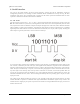
Steps 1 & 2 (write as binary, add 7 zeros to the end of the message):
CRC-7 Polynomial = [1 0 0 0 1 0 0 1]
message = [1 1 0 0 0 0 0 1] [1 0 0 0 0 0 0 0] 0 0 0 0 0 0 0
Qik 2s9v1 User's Guide © 2001–2012 Pololu Corporation
6. Cyclic Redundancy Check (CRC) Error Detection Page 20 of 24