Pololu RC Switch User’s Guide © 2001–2017 Pololu Corporation Pololu RC Switch User’s Guide https://www.pololu.
Pololu RC Switch User’s Guide © 2001–2017 Pololu Corporation 1. Overview . . . . . . . . . . . . . . . . . . . . . . . . . . . . . . . . . . . . 1.1. Contacting Pololu . . . . . . . . . . . . . . . . . . . . . . . . . . . . 2. RC Switch with Digital Output . . . . . . . . . . . . . . . . . . . . . . . . . 2.1. Components of the RC Switch with Digital Output . . . . . . . . . . . 2.2. Connecting the RC Switch with Digital Output . . . . . . . . . . . . . 2.3.
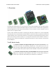
Pololu RC Switch User’s Guide © 2001–2017 Pololu Corporation 1. Overview The Pololu RC switches allow you to turn devices on and off using standard radio control (RC) pulses. These switches can be used with standard hobby RC systems for radio-controlled switch applications. Example applications include using extra channels on an RC receiver or servo controller to turn on lights, motors, or irrigation valves.
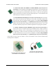
Pololu RC Switch User’s Guide © 2001–2017 Pololu Corporation The Pololu RC Switch with Medium Low-Side MOSFET product/2803] [https://www.pololu.com/ has an integrated low-side MOSFET that allows it to drive moderate loads (up to around 15 A) and a voltage regulator that allows more options for powering the board. The included screw terminal block makes it easy to connect the load and load supply wires directly to the board.
Pololu RC Switch User’s Guide © 2001–2017 Pololu Corporation Note: This guide does not apply to our older RC switches (products #721 [https://www.pololu.com/product/721], #722 [https://www.pololu.com/product/722], #752 [https://www.pololu.com/product/752], #1210 [https://www.pololu.com/product/1210], #1211 [https://www.pololu.com/product/1211]). 1.1. Contacting Pololu We would be delighted to hear from you about any of your projects and about your experience with the RC switch.
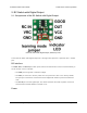
Pololu RC Switch User’s Guide © 2001–2017 Pololu Corporation 2. RC Switch with Digital Output 2.1. Components of the RC Switch with Digital Output Pololu RC Switch with Digital Output, labeled top view. The Pololu RC Switch with Digital Output has 7 through holes spaced 0.1″ apart that fit 0.1″ header pins. RC interface The GND, VRC, and RC IN pins make up the switch’s RC interface and can be connected directly to an RC receiver or servo controller: • The GND pin is the ground or reference voltage.
Pololu RC Switch User’s Guide © 2001–2017 Pololu Corporation The VCC pin powers the basic functions of the board and needs to be connected to a power source between 2.5 V and 5.5 V. The VCC=VRC jumper on the bottom of the board can be bridged with solder to power the board from VRC or to pass power from VCC to the RC receiver. Outputs and indicator LED The RC switch provides feedback about what state it is in via a yellow indicator LED. The LED behavior is described in Section 8.
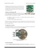
Pololu RC Switch User’s Guide © 2001–2017 Pololu Corporation Pololu RC Switch with Digital Output. The header pins can be soldered in and used to connect the RC switch to perfboards or breadboards [https://www.pololu.com/category/28/solderless-breadboards]. Pololu RC Switch with Digital Output with included hardware. 2.2.
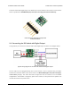
Pololu RC Switch User’s Guide © 2001–2017 Pololu Corporation Power for the switch’s logic needs to be applied to GND and VCC and must be between 2.5 V and 5.5 V. Many microcontroller boards have a 3.3 V or 5 V line that powers the microcontroller and would also be suitable for powering the RC switch. The OUT line can be connected to a digital input pin on the microcontroller. Power jumper The setup described above involves two separate power supplies.
Pololu RC Switch User’s Guide This schematic is also available as a printable pdf © 2001–2017 Pololu Corporation [https://www.pololu.com/file/download/ pololu-rc-switch-with-digital-output-schematic-diagram.PDF?file_id=0J700] 2. RC Switch with Digital Output (126k PDF).
Pololu RC Switch User’s Guide © 2001–2017 Pololu Corporation 3. RC Switch with Small Low-Side MOSFET 3.1. Components of the RC Switch with Small Low-Side MOSFET Pololu RC Switch with Small Low-Side MOSFET, top labeled view. The Pololu RC Switch with Small Low-Side MOSFET has 11 through holes spaced 0.1″ apart that fit 0.1″ header pins.
Pololu RC Switch User’s Guide © 2001–2017 Pololu Corporation This board involves three potentially-different power supplies: • VCC: The VCC pin powers the basic functions of the board and needs to be connected to a power source between 2.5 V and 5.5 V. VCC is also the gate voltage that is used to turn the MOSFET on, so it should be noted that lower VCC voltages will lead to higher MOSFET on resistances, which in turn limits the maximum current the device can switch.
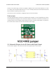
Pololu RC Switch User’s Guide © 2001–2017 Pololu Corporation Configuration interface The learning mode jumper on both the top and bottom of the board can be used to get the device into learning mode and configure it. The configuration procedure is described in Section 9. Pololu RC Switch with Small Low-Side MOSFET, bottom view with dimensions. Included hardware A 12-pin 0.1″ straight breakaway male header [https://www.pololu.
Pololu RC Switch User’s Guide © 2001–2017 Pololu Corporation Pololu RC Switch with Small Low-Side MOSFET with included hardware. 3.2. Connecting the RC Switch with Small Low-Side MOSFET The typical way to connect the Pololu RC Switch with Small Low-Side MOSFET is shown in the diagram below: 3.
Pololu RC Switch User’s Guide © 2001–2017 Pololu Corporation Pololu RC Switch with Small Low-Side MOSFET, typical wiring diagram. The RC switch can be plugged directly into an RC receiver or servo controller using a FemaleFemale servo extension cable. These can be found in our Servo Cables [https://www.pololu.com/category/ 112/servo-cables] category.
Pololu RC Switch User’s Guide © 2001–2017 Pololu Corporation Power jumpers The setup described above involves three separate power supplies. For some applications, this setup can be simplified by bridging one or both of the power jumpers on the bottom of the board. Here are some alternative options for powering your system with fewer than three power supplies: • If the VRC supply from the RC receiver is between 2.5 V and 5.
Pololu RC Switch User’s Guide © 2001–2017 Pololu Corporation 3.3. Schematic Diagram for the RC Switch with Small Low-Side MOSFET The schematic diagram of the Pololu RC Switch with Small Low-Side MOSFET is shown below: This schematic is also available as a printable pdf [https://www.pololu.com/file/download/ pololu-rc-switch-with-small-low-side-mosfet-schematic-diagram.PDF?file_id=0J699] 3. RC Switch with Small Low-Side MOSFET (143k PDF).
Pololu RC Switch User’s Guide © 2001–2017 Pololu Corporation 4. RC Switch with Medium Low-Side MOSFET 4.1. Components of the RC Switch with Medium Low-Side MOSFET Pololu RC Switch with Medium Low-Side MOSFET, labeled top view. The Pololu RC Switch with Medium Low-Side MOSFET has 12 smaller through holes spaced 0.1″ apart that fit 0.1″ header pins and four larger holes that fit 3.5 mm screw terminals.
Pololu RC Switch User’s Guide © 2001–2017 Pololu Corporation VCC is also the gate voltage that is used to turn the MOSFET on, so it should be noted that lower VCC voltages will lead to higher MOSFET on resistances, which in turn limits the maximum current the device can switch. Load interface The LOAD LOW and LOAD HIGH pins are connections for your load and load supply. The LOAD LOW pins are normally disconnected from GND, but when the switch activates the MOSFET turns on and connects LOAD LOW to GND.
Pololu RC Switch User’s Guide © 2001–2017 Pololu Corporation Pololu RC Switch with Medium Low-Side MOSFET, bottom view with dimensions. Included hardware A 12-pin 0.1″ straight breakaway male header [https://www.pololu.com/product/965] and two 3.5 mm 2-pin terminal blocks [https://www.pololu.com/product/2446] are included with the Pololu RC Switch with Medium Low-Side MOSFET. The header pins can be soldered in and used to connect the RC switch to perfboards or breadboards [https://www.pololu.
Pololu RC Switch User’s Guide © 2001–2017 Pololu Corporation Pololu RC Switch with Medium Low-Side MOSFET with included hardware. 4.2. Connecting the RC Switch with Medium Low-Side MOSFET The typical way to connect the Pololu RC Switch with Medium Low-Side MOSFET is shown in the diagram below: 4.
Pololu RC Switch User’s Guide © 2001–2017 Pololu Corporation Typical wiring diagram for the Pololu RC Switch with Medium Low-Side MOSFET. An onboard regulator allows the switch to be powered from voltages between 2.5 V and 16 V. However, for most applications we recommend using a 4- or 5-cell NiMH or NiCD battery pack to power the switch. The battery pack will typically be connected to an RC receiver or servo controller [https://www.pololu.
Pololu RC Switch User’s Guide © 2001–2017 Pololu Corporation handle load supply voltages up to 30 V. For lower power applications the smaller 0.1″-spaced pins can be used instead of the terminal block to connect the load and load supply. Pololu RC Switch with Medium LowSide MOSFET with included terminal blocks and headers soldered to the component side. Pololu RC Switch with Medium LowSide MOSFET on a breadboard. 4.3.
Pololu RC Switch User’s Guide This schematic is also available as a printable pdf © 2001–2017 Pololu Corporation [https://www.pololu.com/file/download/ pololu-rc-switch-with-medium-low-side-mosfet-schematic-diagram.pdf?file_id=0J684] 4. RC Switch with Medium Low-Side MOSFET (156k pdf).
Pololu RC Switch User’s Guide © 2001–2017 Pololu Corporation 5. RC Switch with Relay 5.1. Components of the RC Switch with Relay Pololu RC Switch with Relay, labeled top view. The Pololu RC Switch with Relay has five pins spaced 0.1″ apart that give access to its logic interface. RC interface The GND, VRC, and RC IN pins make up the switch’s RC interface and can be connected directly to an RC receiver or servo controller: • The GND pin is the ground or reference voltage.
Pololu RC Switch User’s Guide © 2001–2017 Pololu Corporation Relay interface The NO, NC, and COM pins are connected directly to the relay. • NO stands for “normally open”. This pin is normally disconnected from the COM pin, but they become connected when the relay is active. • NC stands for “normally connected”. The NC pin is normally connected to the COM pin through the relay, but they become disconnected when the relay is active. • COM stands for “common”.
Pololu RC Switch User’s Guide © 2001–2017 Pololu Corporation Configuration interface The learning mode jumper can be used to get the device into learning mode and configure it. The configuration procedure is described in Section 9. Pololu RC Switch with Relay carrier board, labeled top view. Pololu RC Switch with Relay, bottom view with dimensions. Included hardware The Pololu RC Switch with Relay is available in two versions: 5.
Pololu RC Switch User’s Guide • The assembled version © 2001–2017 Pololu Corporation [https://www.pololu.com/product/2804] ships with the 5V Omron relay, header pins, and terminal block soldered in. A 1×2-pin male header and a shorting block are also included with the assembled version and can be used together as a tool when configuring the device. The assembled version can be incorporated into an existing RC system without the need for any additional soldering. • The partial kit version [https://www.
Pololu RC Switch User’s Guide © 2001–2017 Pololu Corporation Typical wiring diagram for the Pololu RC Switch with Relay. We generally recommend that you use a 4- or 5-cell NiMH or NiCD battery pack for the logic power supply. The power supply will typically be connected to the RC receiver, which passes the power on to the RC switch. The switch can be plugged directly into the RC receiver using a Female-Female servo extension cable. These can be found in our Servo Cables [https://www.pololu.
Pololu RC Switch User’s Guide © 2001–2017 Pololu Corporation The Pololu RC Switch with Relay connected to a typical RC receiver. 5.3. Schematic Diagram for the RC Switch with Relay The schematic diagram of the Pololu RC Switch with Relay is shown below: 5.
Pololu RC Switch User’s Guide This schematic is also available as a printable pdf © 2001–2017 Pololu Corporation [https://www.pololu.com/file/download/ pololu-rc-switch-with-relay-schematic-diagram.pdf?file_id=0J682] 5. RC Switch with Relay (165k pdf).
Pololu RC Switch User’s Guide © 2001–2017 Pololu Corporation 6. Pololu 4-Channel RC Servo Multiplexer 6.1. Components of the 4-Channel RC Servo Multiplexer Pololu 4-Channel RC Servo Multiplexer (Assembled), labeled pinout. RC interface The Pololu 4-Channel RC Servo Multiplexer has a total of 13 RC servo channels: • The four inputs M1–M4 are called the master inputs. • The four inputs S1–S4 are called the slave inputs. • The four outputs OUT1–OUT4 are the main outputs of the device.
Pololu RC Switch User’s Guide © 2001–2017 Pololu Corporation When the RC signal on the SEL channel is lost or invalid, the optional FAILMODE jumper determines the output behavior. If the jumper is left off, the master inputs will be in control. If the jumper is connected, the output channels go low and stay low for as long as the signal on the SEL channel remains invalid.
Pololu RC Switch User’s Guide © 2001–2017 Pololu Corporation Configuration interface The learning mode jumper can be used to get the device into learning mode and configure it. The configuration procedure is described in Section 9. Pololu 4-Channel RC Servo Multiplexer, bottom view with dimensions. Included hardware The Pololu 4-Channel RC Servo Multiplexer is available in two versions: • The assembled version [https://www.pololu.
Pololu RC Switch User’s Guide Pololu 4-Channel RC Multiplexer (Assembled). © 2001–2017 Pololu Corporation Pololu 4-Channel RC Servo Multiplexer (Partial Kit) with included hardware. 6.2. Connecting the 4-Channel RC Servo Multiplexer The RC multiplexer pins are spaced 0.1″ apart so the servo inputs can be plugged directly into an RC receiver or servo controller using a Female-Female servo extension cable. These can be found in our Servo Cables [https://www.pololu.com/category/112/servo-cables] category.
Pololu RC Switch User’s Guide This schematic is also available as a printable pdf © 2001–2017 Pololu Corporation [https://www.pololu.com/file/download/ pololu-4-channel-rc-servo-multiplexer-schematic-diagram.pdf?file_id=0J701] 6. Pololu 4-Channel RC Servo Multiplexer (210k pdf).
Pololu RC Switch User’s Guide © 2001–2017 Pololu Corporation 7. Functional Description This section documents the functions and behavior of the RC switch. The information in this section is not needed to use the device, but it might be helpful if you are curious about the details. Timing accuracy The timing accuracy of the RC switch is limited by its internal clock, which has an accuracy of ±2%. Because of this, the threshold and other timing parameters might vary by a few percent.
Pololu RC Switch User’s Guide © 2001–2017 Pololu Corporation If the device is receiving a valid RC signal which suddenly stops, it will take 130 ms before the signal is recognized as bad. From there, it will take 500 ms before the safe-start mode becomes active, so there will be a total of 630 ms between the loss of the signal and the re-activation of safe-start mode. To get out of safe-start mode and activate the switch, you should move the input to the off position and then move it to the on position.
Pololu RC Switch User’s Guide © 2001–2017 Pololu Corporation 8. Outputs and Indicator LED The OUT pin is an output that indicates whether the switch is active. A high value means the switch is active, and a low value means it is not active. The OUT pin is high whenever the integrated MOSFET or relay is turned on. The Pololu 4-Channel RC Multiplexer does not have an OUT pin, but the same signal could be accessed by soldering a wire to the board as described in Section 6.1.
Pololu RC Switch User’s Guide © 2001–2017 Pololu Corporation 9. Configuring Your RC Switch The RC switch has two user-settable configuration parameters, threshold and inversion, which are described in Section 7. This section and the following sections explain how to set both parameters. To configure the device, you will need to be able to connect and disconnect the two parts of the learning mode jumper. This will be required at several points by the instructions in the following sections.
Pololu RC Switch User’s Guide © 2001–2017 Pololu Corporation Pololu RC Switch with Medium Low-Side MOSFET, labeled top view. For the Pololu RC Switch with Medium Low-Side MOSFET, the learning mode jumper consists of a pair of exposed pads on the component side of the board. An alternate learning mode jumper is available on the other side of the board and is labeled “LRN”; you can use whichever jumper is more convenient.
Pololu RC Switch User’s Guide © 2001–2017 Pololu Corporation Pololu RC Switch with Relay, labeled top view. For the Pololu RC Switch with Relay, the learning mode jumper consists of two holes. You could use a wire to connect the two holes, but we recommend inserting a 1×2-pin male header into the included blue shorting block and using that as a tool to connect the two holes. The assembled version of the switch comes with a 1×2-pin male header.
Pololu RC Switch User’s Guide © 2001–2017 Pololu Corporation Pololu 4-Channel RC Servo Multiplexer (Assembled), labeled pinout. For the Pololu 4-Channel RC Servo Multiplexer, the learning mode jumper consists of a pair of exposed pads on the component side of the board. An alternate learning mode jumper is available on the other side of the board and is labeled “LEARN”; you can use whichever jumper is more convenient.
Pololu RC Switch User’s Guide © 2001–2017 Pololu Corporation 3. Now the device is in the pulse-measuring phase of learning mode. This is where you can choose what threshold to use. ◦ If you want to use the default threshold, you should not send RC pulses to the device. The device will indicate that the RC input signal is not recognized by blinking the LED with a 50% duty cycle and a period of 0.5 s. ◦ If you want to use a custom threshold, you should send RC pulses to the device.
Pololu RC Switch User’s Guide © 2001–2017 Pololu Corporation the learning mode jumper. At this point, you will see the indicator LED fading in and out with a period of 1 second. 2. Tap the learning mode jumper (connect it and then disconnect it). The indicator LED should be blinking a different pattern now. 3. Power off the device to exit learning mode. After following these instructions, the threshold should be 1696 μs and inversion should be disabled. 9.3.