Tic Stepper Motor Controller User’s Guide © 2001–2018 Pololu Corporation Tic Stepper Motor Controller User’s Guide https://www.pololu.
Tic Stepper Motor Controller User’s Guide 1. Overview . . . . . . . . . . . . . . . . . . . . . . . . . . 1.1. Available versions . . . . . . . . . . . . . . . . . . 1.2. Supported operating systems . . . . . . . . . . . . 2. Contacting Pololu . . . . . . . . . . . . . . . . . . . . . . 3. Getting started . . . . . . . . . . . . . . . . . . . . . . . 3.1. Installing Windows drivers and software . . . . . . 3.2. Installing Linux software . . . . . . . . . . . . . . . 3.3. Installing macOS software . . . . .
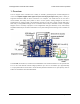
Tic Stepper Motor Controller User’s Guide © 2001–2018 Pololu Corporation 1. Overview The Tic stepper motor controllers are a family of versatile, general-purpose modules designed to control one bipolar stepper motor [https://www.pololu.com/category/87/stepper-motors].
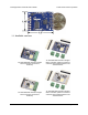
Tic Stepper Motor Controller User’s Guide © 2001–2018 Pololu Corporation The Tic T834, shown above, is based on the DRV8834 IC from Texas Instruments. It can operate from 2.5 V to 10.8 V and features reverse-voltage protection over the full input voltage range. It can deliver up to approximately 1.5 A per phase without a heat sink or forced air flow (absolute maximum is 2 A per phase). The Tic T834’s circuit board is white with black labels.
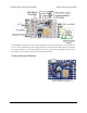
Tic Stepper Motor Controller User’s Guide © 2001–2018 Pololu Corporation • Open-loop speed or position control of one bipolar stepper motor • A variety of control interfaces: ◦ USB for direct connection to a computer ◦ TTL serial operating at 5 V for use with a microcontroller ◦ I²C for use with a microcontroller ◦ RC hobby servo pulses for use in an RC system ◦ Analog voltage for use potentiometer or analog joystick with Tic T825 USB Multi-Interface Stepper Motor Controller (bottom view).
Tic Stepper Motor Controller User’s Guide © 2001–2018 Pololu Corporation 1.1. Available versions Tic T825 USB Multi-Interface Stepper Motor Controller (Connectors Soldered). Tic T825 USB Multi-Interface Stepper Motor Controller (without connectors soldered) with included headers and terminal blocks. Tic T834 USB Multi-Interface Stepper Motor Controller (Connectors Soldered). Tic T834 USB Multi-Interface Stepper Motor Controller (without connectors soldered) with included headers and terminal blocks.
Tic Stepper Motor Controller User’s Guide © 2001–2018 Pololu Corporation The Tic family consists of two different controllers: the Tic T825 and Tic T834. The main differences between those boards are mentioned in Section 1. The Tic T825 and Tic T834 controllers are each available in two versions: with terminal blocks and 0.1″ male headers installed, as shown in the left pictures above, and with through-hole connectors included but not soldered in, as shown in the right pictures above.
Tic Stepper Motor Controller User’s Guide © 2001–2018 Pololu Corporation platforms. 1.
Tic Stepper Motor Controller User’s Guide © 2001–2018 Pololu Corporation 2. Contacting Pololu We would be delighted to hear from you about any of your projects and about your experience with the Tic Stepper Motor Controller. You can contact us [https://www.pololu.com/contact] directly or post on our forum [https://forum.pololu.com/]. Tell us what we did well, what we could improve, what you would like to see in the future, or anything else you would like to say! 2.
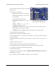
Tic Stepper Motor Controller User’s Guide © 2001–2018 Pololu Corporation 3. Getting started 3.1. Installing Windows drivers and software To install the drivers and software for the Tic on a computer running Microsoft Windows, follow these steps: 1. Download and install the Tic Software and Drivers for Windows [https://www.pololu.com/file/ download/pololu-tic-1.4.0-win.msi?file_id=0J1325] (9MB msi). 2. During the installation, Windows will ask you if you want to install the drivers.
Tic Stepper Motor Controller User’s Guide © 2001–2018 Pololu Corporation no entries, then the tips here can help you troubleshoot the Tic’s USB connection on a Windows computer. If you have connected any electronic devices to your Tic besides the USB cable, you should disconnect them. You should look at the LEDs of the Tic. If the LEDs are off, then the Tic is probably not receiving power from the USB port.
Tic Stepper Motor Controller User’s Guide © 2001–2018 Pololu Corporation The Status tab of the Pololu Tic Control Center. 3.2. Installing Linux software To install the software for the Tic on a computer running Linux, follow these steps: 1. Download the version for your system from this list: ◦ Tic Software for Linux (x86) x86.tar.xz?file_id=0J1348] [https://www.pololu.com/file/download/pololu-tic-1.4.0-linux- (8MB xz) — works on 32-bit and 64-bit systems ◦ Tic Software for Linux (Raspberry Pi) tic-1.
Tic Stepper Motor Controller User’s Guide © 2001–2018 Pololu Corporation asterisk. 4. Run sudo pololu-tic/install.sh to install the software. You will need to have sudo privilege on your system and you might need to type your password at this point. Look at the output of the script to see if any errors happened. 5. After the installation has completed, plug the Tic into your computer via USB.
Tic Stepper Motor Controller User’s Guide © 2001–2018 Pololu Corporation echo $PATH to see what directories are on your PATH, and then make sure one of those directories contains the Tic executables or symbolic links to them. The installer puts symbolic links in /usr/local/ bin , so if that directory is not on your PATH, you should run export PATH=$PATH:/usr/local/bin to add it. Also, you might want to put that line in your ~/.profile file so the directory will be on your PATH in future sessions.
Tic Stepper Motor Controller User’s Guide © 2001–2018 Pololu Corporation If you get a “Permission denied” error when trying to connect to the Tic, you should make sure to copy the 99-pololu.rules file into /etc/udev/rules.d and then unplug the Tic and plug it back in again. The install script normally takes care of installing that file for you. If that does not help, you should try running lsusb to list the USB devices recognized by your computer. Look for the Pololu vendor ID, which is 1ffb.
Tic Stepper Motor Controller User’s Guide © 2001–2018 Pololu Corporation 3.4. LED feedback The Tic Stepper Motor Controller has three LEDs to indicate its status. The green LED indicates the USB status of the device. When you connect the Tic to a computer via a USB cable, the green LED will start blinking slowly. The blinking continues until the Tic gets a particular message from the computer that indicates that the Tic is recognized.
Tic Stepper Motor Controller User’s Guide © 2001–2018 Pololu Corporation ◦ If the motor is energized and a safe start violation is only error happening, then the yellow LED will stay on most of the time, but will periodically blink off once: • If the stepper motor coils are de-energized, then the yellow LED will be off most of the time. ◦ If there is a motor driver error (i.e.
Tic Stepper Motor Controller User’s Guide © 2001–2018 Pololu Corporation moving, or if it is even connected. The LED blinking patterns above are based on the signals that the Tic is sending to the on-board stepper motor driver. To ensure that the Tic shows a complete blinking pattern instead of switching quickly between two or more patterns, the yellow LED blinking pattern is only updated after it has completed.
Tic Stepper Motor Controller User’s Guide © 2001–2018 Pololu Corporation 4. Setting up the controller 4.1. Choosing the power supply, Tic, and stepper motor The information in this section can help you select a power supply 84/regulators-and-power-supplies], stepper-motors] [https://www.pololu.com/category/ a Tic controller, and a stepper motor [https://www.pololu.com/category/87/ that will work well together. Stepper motor configurations There are different types of stepper motors.
Tic Stepper Motor Controller User’s Guide © 2001–2018 Pololu Corporation The operating voltage range of a Tic is the range of voltages from which it can be powered. The operating voltages of the different Tic controllers are shown in the table below. The Tic requires a DC power supply. The continuous current per phase of a Tic is the maximum amount of current that the Tic can continuously provide to each phase of the stepper motor.
Tic Stepper Motor Controller User’s Guide © 2001–2018 Pololu Corporation continuous current rating whenever you move the motor, and reducing it while the motor is holding position, thus maintaining a low average current.) If the motor’s rated current is substantially more than the Tic’s current, then it is possible that the Tic will not be able to move the motor at all. 5.
Tic Stepper Motor Controller User’s Guide © 2001–2018 Pololu Corporation Warning: This product is not designed to or certified for any particular high-voltage safety standard. Working with voltages above 30 V can be extremely dangerous and should only be attempted by qualified individuals with appropriate equipment and protective gear. Warning: Connecting or disconnecting a stepper motor while the Tic’s motor power supply (VIN) is powered can destroy the motor driver.
Tic Stepper Motor Controller User’s Guide Connecting a two-phase bipolar stepper motor with four (4) leads to the Tic. © 2001–2018 Pololu Corporation Connecting a two-phase unipolar/ bipolar stepper motor with six (6) leads to the Tic. The two center taps are left disconnected. Swapping A1 with A2 or B1 with B2 in the above diagrams just reverses the direction of the motor. Swapping both will leave the direction unchanged.
Tic Stepper Motor Controller User’s Guide Connecting a two-phase unipolar/ bipolar stepper motor with eight (8) leads to the Tic with the phase coils in parallel. © 2001–2018 Pololu Corporation Connecting a two-phase unipolar/ bipolar stepper motor with eight (8) leads to the Tic with the phase coils in series.
Tic Stepper Motor Controller User’s Guide © 2001–2018 Pololu Corporation The default motor settings for the Tic T825. The default motor settings for the Tic T834 are the same except for the decay mode, which is “Mixed 50%” by default. Setting the current limit Assuming that you are not limited by the Tic or your power supply, we recommend setting the current limit of the Tic to the rated current of your motor.
Tic Stepper Motor Controller User’s Guide © 2001–2018 Pololu Corporation selected will start flowing through the coils, and the message at the bottom of the screen should change to “Driving”. If your power supply cannot supply enough current, its voltage might dip when you click the “Resume” button. The Tic will detect that VIN has dropped too low (7.0 V for the Tic T825, 2.1 V for the Tic T834), report a “Low VIN” error, and de-energize the motor.
Tic Stepper Motor Controller User’s Guide © 2001–2018 Pololu Corporation takes 200 of these full steps to rotate 360 degrees. Allowed coil current transitions in full step mode. Arrows to the right correspond to one motor rotation direction and arrows to the left correspond to the other.
Tic Stepper Motor Controller User’s Guide © 2001–2018 Pololu Corporation In the other available step modes, the Tic uses microsteps instead of full steps to generate magnetic fields that point to places between the full steps. Each microstep corresponds to 1/2, 1/4, 1/8, 1/16, or 1/32 of a full step, depending on what step mode you choose.
Tic Stepper Motor Controller User’s Guide © 2001–2018 Pololu Corporation current through the other coil is zero. The Tic’s speed, velocity, acceleration, and deceleration numbers are all denominated in microsteps, which are also called pulses. Therefore, if you change the step mode, you might have to change those other settings to account for the change. For example, the default maximum speed for the Tic is 200 pulses per second.
Tic Stepper Motor Controller User’s Guide © 2001–2018 Pololu Corporation The “Set target” box in the Tic Control Center, with its range set to plus or minus 400 pulses per second. Try slowly dragging the scrollbar to both ends of its range. If your motor is able to reach the desired speeds without pausing or skipping, you can increase the range of the scrollbar and try again. By experimenting with the velocity scrollbar, you should be able to get an idea of what your motor can do.
Tic Stepper Motor Controller User’s Guide © 2001–2018 Pololu Corporation then the Tic will be able to instantly change from any velocity in the range of −1000000 to +1000000 to any other velocity in that range. Setting the starting speed might allow you to make your system faster since it will not waste time accelerating or decelerating through low speeds where it is not needed. 4.4. Setting up USB control This section explains how to control the Tic over USB.
Tic Stepper Motor Controller User’s Guide © 2001–2018 Pololu Corporation You might notice that the Tic only performs the desired movement for about a second before it stops moving and the red LED turns on, indicating an error. This is because of the Tic’s command timeout feature: by default, the Tic’s “Command timeout” error will happen if it does not receive certain commands periodically (see Section 5.4 for details), causing the motor to stop.
Tic Stepper Motor Controller User’s Guide © 2001–2018 Pololu Corporation Diagram of a non-inverted TTL serial byte. The serial lines are high by default. The beginning of a transmitted byte is signaled with a single low start bit, followed by the bits of byte, least-significant bit (LSB) first. The byte is terminated by a stop bit, which is the line going high for at least one bit time.
Tic Stepper Motor Controller User’s Guide © 2001–2018 Pololu Corporation levels. You can try connecting the device’s TX line directly to the Tic’s RX line; this will usually work, but the input signal on the RX pin must reach at least 4 V to be guaranteed to be read as high. If you want to read data from the Tic, you will need to consider how to connect the Tic’s TX line to your device’s RX line.
Tic Stepper Motor Controller User’s Guide © 2001–2018 Pololu Corporation Optional connections The Tic’s 5V (out) pin provides access to the output of the Tic’s 5V regulator, which also powers the Tic’s microcontroller and the red and yellow LEDs. You can use the Tic’s regulator to power your microcontroller or other serial device if the device does not draw too much current (see Section 5.7).
Tic Stepper Motor Controller User’s Guide © 2001–2018 Pololu Corporation uses device numbers 14 and 15: 1 2 ? TicSerial tic1(ticSerial, 14); TicSerial tic2(ticSerial, 15); If you want to read data from multiple Tics, you cannot simply connect all of the Tic TX lines together, because when one of Tics tries to drive its TX line low to send data, the TX lines from the other Tics will still be driving the line high and will prevent the signal from going all the way to 0 V.
Tic Stepper Motor Controller User’s Guide © 2001–2018 Pololu Corporation More information about the serial interface This user’s guide has more information about the Tic’s commands (Section 8) and serial protocol (Section 9). 4.6. Setting up I²C control This section explains how to connect a microcontroller to the Tic’s I²C interface so that you can send commands to control the Tic. The Tic Stepper Motor Controller library for Arduino [https://github.
Tic Stepper Motor Controller User’s Guide © 2001–2018 Pololu Corporation Because the Tic considers an input value of 2.1 V on SCL or SDA to be high, you can connect those pins directly to 3.3 V microcontrollers without needing a level shifter. If your microcontroller’s I²C interface is not 5V tolerant, it will usually still have a diode going from each I/O pin to its logic supply. These diodes clamp the voltage on the pins, preventing the Tic’s pull-up resistors from pulling the pins too high.
Tic Stepper Motor Controller User’s Guide © 2001–2018 Pololu Corporation forth. If the stepper motor is not moving, you should check all of your connections and solder joints (if applicable). You should check the “Status” tab of the Tic Control Center to see if any errors are being reported. You can also try slowing down your I²C clock speed to something very slow like 1 kHz or 10 kHz.
Tic Stepper Motor Controller User’s Guide 1 2 TicI2C tic1(14); TicI2C tic2(15); © 2001–2018 Pololu Corporation ? The following diagram shows the standard I²C connections described above along with optional connections of the ERR and RST pins: The ERR pins can all be safely connected together. In such a configuration, the line will be high if one or more Tics has an error; otherwise, it will be low.
Tic Stepper Motor Controller User’s Guide © 2001–2018 Pololu Corporation If you have not done so already, you should follow the instructions in Section 4.3 to configure and test your stepper motor. Next, with the system unpowered, connect your RC receiver to the Tic’s GND, 5V, and RC pins as shown in the diagram below. In this configuration, the RC receiver will be powered by the Tic’s 5 V regulator via the 5V output pin.
Tic Stepper Motor Controller User’s Guide © 2001–2018 Pololu Corporation Now connect the Tic to your computer via USB. In the Tic Control Center software, set the Tic’s control mode to “RC position” and click “Apply settings”. In the “Scaling” box, click “Learn…” to start the Input Setup Wizard. The wizard will help you measure the neutral, maximum, and minimum positions of your RC signal.
Tic Stepper Motor Controller User’s Guide © 2001–2018 Pololu Corporation In this mode, the Tic will behave like an electronic speed controller (ESC), except with a stepper motor instead of a DC motor. If you have not done so already, you should follow the instructions in Section 4.3 to configure and test your stepper motor. Next, with the system unpowered, connect your RC receiver to the Tic’s GND, 5V, and RC pins as shown in the diagram below.
Tic Stepper Motor Controller User’s Guide © 2001–2018 Pololu Corporation Now connect the Tic to your computer via USB. In the Tic Control Center software, set the Tic’s control mode to “RC speed” and click “Apply settings”. In the “Scaling” box, click “Learn…” to start the Input Setup Wizard. The wizard will help you measure the neutral, maximum, and minimum positions of your RC signal.
Tic Stepper Motor Controller User’s Guide © 2001–2018 Pololu Corporation Section 5.2. 4.9. Setting up analog position control This section explains how to set up the Tic to read an analog input and use that signal to control the position of the stepper motor. It is important to note that the Tic does not receive any kind of feedback from the stepper motor about its position.
Tic Stepper Motor Controller User’s Guide © 2001–2018 Pololu Corporation mode to “Analog position” and click “Apply settings”. In the “Scaling” box, click “Learn…” to start the Input Setup Wizard. The wizard will help you measure the neutral, maximum, and minimum positions of your analog signal.
Tic Stepper Motor Controller User’s Guide © 2001–2018 Pololu Corporation For details about how the input scaling works, see Section 5.2. 4.10. Setting up analog speed control This section explains how to set up the Tic to read an analog input and use that signal to control the speed of the stepper motor. If you have not done so already, you should follow the instructions in Section 4.3 to configure and test your stepper motor.
Tic Stepper Motor Controller User’s Guide © 2001–2018 Pololu Corporation minimum. You should change the target maximum to be equal to the maximum velocity that you want your motor to move in the forward/positive direction. Since you already set the “Max speed” parameter in the “Motor” box (see Section 4.3), you could just copy that value into the target maximum box. If you want your motor to go the same speed in both directions, you should set the target minimum to the negative of the target maximum.
Tic Stepper Motor Controller User’s Guide © 2001–2018 Pololu Corporation 4.11. Setting up encoder position control This section explains how to set up the Tic to read signals from a quadrature encoder and use them to control the position of the stepper motor. The Tic does not support closed-loop control with encoder feedback. The Tic’s encoder input is meant to be connected to a rotary encoder that is turned by hand.
Tic Stepper Motor Controller User’s Guide © 2001–2018 Pololu Corporation ground as the dial is rotated. The built-in pull-ups on the RX and TX pins make the signal high during the times when the encoder outputs are floating, so there is no need for external pull-ups. Other kinds of quadrature encoders might require power, and the 5V output on the Tic can be used to power them if their documentation indicates they can operate at 5 V.
Tic Stepper Motor Controller User’s Guide © 2001–2018 Pololu Corporation If you have access to an oscilloscope, you should check the signals on RX and TX. If the “Encoder position” is responding properly to the encoder but the “Input after scaling” variable is not, then make sure you have set those settings to their defaults as described above. The Tic expects that transitions on its encoder inputs will be at least 100 µs apart.
Tic Stepper Motor Controller User’s Guide © 2001–2018 Pololu Corporation The Tic does not support closed-loop control with encoder feedback. The Tic’s encoder input is meant to be connected to a rotary encoder that is turned by hand. If you have a stepper motor with an integrated encoder, you should not try to connect the motor’s encoder to the Tic. If you have not done so already, you should follow the instructions in Section 4.3 to configure and test your stepper motor.
Tic Stepper Motor Controller User’s Guide © 2001–2018 Pololu Corporation As a first step, you should turn off the power to your system and then connect your encoder to the Tic as described above and shown in the diagram below. You can swap your A and B connections to flip the direction of the encoder. Now connect the Tic to your computer via USB. In the Tic Control Center software, set the Tic’s control mode to “Encoder speed”.
Tic Stepper Motor Controller User’s Guide © 2001–2018 Pololu Corporation applicable). If you have access to an oscilloscope, you should check the signals on RX and TX. If the “Encoder position” is responding properly to the encoder but the “Input after scaling” variable is not, then make sure you set the Tic’s input settings as described above.
Tic Stepper Motor Controller User’s Guide © 2001–2018 Pololu Corporation The STEP and DIR lines are pulled down by default. The driver takes one step whenever it sees a rising edge on the STEP pin, and the direction of the step is specified by the DIR pin. See the DRV8825 datasheet [https://www.pololu.com/file/download/drv8825.pdf?file_id=0J590] (1MB pdf) for detailed specifications of the STEP/DIR interface on the Tic T825, or see the DRV8834 datasheet [https://www.pololu.com/file/download/drv8834.
Tic Stepper Motor Controller User’s Guide © 2001–2018 Pololu Corporation 5. Details 5.1. Motion parameters This section explains the Tic settings and variables that directly control the motion of the stepper motor. Position The Tic represents stepper motor positions in units of microsteps, which are also called pulses. The number of microsteps that correspond to one full step is determined by the “step mode” setting.
Tic Stepper Motor Controller User’s Guide © 2001–2018 Pololu Corporation is moving at speed 10 and you want it to go 1% faster, you cannot simply change your speed to 10.1; your options would be 10 or 11. For speeds higher than 50 (1 pulse every 200 seconds), the inaccuracy caused by this is less than 1%. High speed considerations If you are trying to use high speeds, it is important to consider how fast your stepper motor is capable of moving. See Section 4.
Tic Stepper Motor Controller User’s Guide © 2001–2018 Pololu Corporation the speed/acceleration/deceleration limits described later in this section. In “Target velocity mode”, the Tic has a variable called “Target velocity” that specifies the velocity the Tic should maintain. It will plan steps so that its current velocity reaches the target velocity, while respecting the limits described later in this section.
Tic Stepper Motor Controller User’s Guide © 2001–2018 Pololu Corporation This setting can be temporarily overridden using the “Set starting speed” command, as described in Section 8. The “Starting speed” uses the Tic’s standard speed units of 10,000 pulses per second. Max acceleration and max deceleration The “Max acceleration” setting specifies how rapidly the speed is allowed to increase, while the “Max deceleration” setting specifies how rapidly the speed is allowed to decrease. See Section 4.
Tic Stepper Motor Controller User’s Guide © 2001–2018 Pololu Corporation The signal should be low (0 V) normally and have periodic pulses with an amplitude (V) of at least 2 V. The width of the pulses (t) should be between 200 µs and 2700 µs. The period of the signal (T), should be at most 100 ms, and the there is no particular lower limit. When the Tic has received three good pulses in a row, it writes the width of the latest pulse to the “RC pulse width” variable in units of 1/12 µs.
Tic Stepper Motor Controller User’s Guide © 2001–2018 Pololu Corporation This feature is turned off by default, but can be turned on by entering a value of 2 or more into the “Input hysteresis” setting in the “Input conditioning” box of Tic Control Center. When the hysteresis value is 2 or more, the Tic essentially takes the “Input after averaging” variable and maps it to the nearest number that is a multiple of the “Input hysteresis” value.
Tic Stepper Motor Controller User’s Guide © 2001–2018 Pololu Corporation Input after averaging, Control mode Input averaging enabled Input after hysteresis, Input before scaling Input hysteresis Analog Yes 15-bit 12-bit Analog No 13-bit 12-bit RC Yes 1/12 µs 2/3 µs RC No 1/12 µs 2/3 µs RC and analog scaling The settings in the “RC and analog scaling” box of the Tic Control Center determine how the “Input before scaling” variable gets mapped to a signed 32-bit integer that will either be used a
Tic Stepper Motor Controller User’s Guide © 2001–2018 Pololu Corporation This graph shows how the Tic’s RC/analog input is scaled to produce a target position or target velocity (input direction not inverted). 5.
Tic Stepper Motor Controller User’s Guide © 2001–2018 Pololu Corporation This graph shows how the Tic’s RC/analog input is scaled to produce a target position or target velocity (input direction inverted). When the “Invert input direction” checkbox is not checked, the input values are mapped to output/ target values according to these rules: 5.
Tic Stepper Motor Controller User’s Guide © 2001–2018 Pololu Corporation • Any input value greater than the input maximum gets mapped to the target maximum. • Any input value between the input neutral max and the input maximum gets mapped to a number between 0 and the target maximum. • Any input value between the input neutral min and input neutral max gets mapped to 0. • Any input value between the input minimum and input neutral min gets mapped to a number between the target minimum and 0.
Tic Stepper Motor Controller User’s Guide © 2001–2018 Pololu Corporation the “Input state” variable is encoded, see Section 7. 5.3. Encoder input handling This section explains the details of how the Tic reads quadrature encoder signals and converts them to a target position or velocity. The Tic does not support closed-loop control with encoder feedback. The Tic’s encoder input is meant to be connected to a rotary encoder that is turned by hand to control the stepper motor’s position or speed.
Tic Stepper Motor Controller User’s Guide © 2001–2018 Pololu Corporation The time between the channel transitions (labeled T1-4 in the diagram above) must be at least 100 µs. The signal must rise to 4 V or higher, and must stay within 0 V to 5 V. The Tic stores the raw encoder counts in the “Encoder position” variable. This variable can be read over serial, I²C, or USB, and it is displayed in the “Status” tab of the Tic control center.
Tic Stepper Motor Controller User’s Guide © 2001–2018 Pololu Corporation The unbounded position control option can only be enabled when the control mode is “Encoder position”, not “Encoder speed”. With this option enabled, the “Input after scaling” can overflow and wrap around from +2,147,483,647 to −2,147,483,648. When the Tic’s control mode is “Encoder position”, the Tic sets it target position equal to the “Input after scaling” variable described above.
Tic Stepper Motor Controller User’s Guide © 2001–2018 Pololu Corporation go into the corresponding operation state as shown in the table above. If multiple conditions are happening, the Tic will choose the first state (the highest state in the table above) that has an active condition. If no conditions are happening, the Tic will proceed with normal operation. After the Tic determines what operation state it is in, it performs the corresponding effects for that operation state as listed in the table.
Tic Stepper Motor Controller User’s Guide © 2001–2018 Pololu Corporation voltage. On the Tic T825, the minimum operating voltage is 8.5 V, and the threshold for the “Low VIN” error is fixed at 7.0 V. On the Tic T834, the minimum operating voltage is 2.5 V, and the threshold for the “Low VIN” error is fixed at 2.1 V. Condition: Intentionally de-energized The “Intentionally de-energized” error bit is 0 when the Tic starts up.
Tic Stepper Motor Controller User’s Guide © 2001–2018 Pololu Corporation “Serial framing” bit in the “Errors occurred” variable to be set.) In a non-serial control mode, serial errors do not cause the Tic to shut down because the serial error will never get set. However, the serial-related bits in the “Errors occurred” register will still be set, so you can detect serial errors in non-serial control modes.
Tic Stepper Motor Controller User’s Guide © 2001–2018 Pololu Corporation after scaling” variable (which represents the target velocity being commanded by the Tic’s main input source) is non-zero. This way, the Tic will never automatically start moving the motor just because all the error conditions have been resolved; it will only start moving the motor if you first put its main input in the neutral position (which maps to a speed of 0), and then move its main input away from the neutral position.
Tic Stepper Motor Controller User’s Guide © 2001–2018 Pololu Corporation signals from other devices. It is pulled low by the LED and a 100 kΩ pull-down resistor. The voltage on the Tic’s microcontroller pin must reach at least 2 V for the input to be guaranteed to read as high. Schematic diagram of the Tic ERR pin when it is acting as an output (i.e. there are errors). Schematic diagram of the Tic ERR pin when it is acting as an input (i.e. there are no errors).
Tic Stepper Motor Controller User’s Guide © 2001–2018 Pololu Corporation high) and stop sending step pulses to the driver. The current flowing through the motor coils will stop. Effect: Drive ERR line high When the Tic is experiencing any error (except for the “ERR line high” error), the Tic will drive its ERR line high, which causes its red LED to turn on. Effect: Reset driver In the “Reset” operation state, the Tic will reset its stepper motor driver IC.
Tic Stepper Motor Controller User’s Guide © 2001–2018 Pololu Corporation Effect: Energize During normal operation or while it is starting up, the Tic will energize the stepper motor coils by enabling its stepper motor driver. Effect: Obey input During normal operation, the Tic sets the stepper motor’s “Target position” or “Target velocity” as specified by its main input. The motion specified by the main input is held in the “Input state” and “Input after scaling” variables.
Tic Stepper Motor Controller User’s Guide © 2001–2018 Pololu Corporation Example pin configuration settings for a Tic Stepper Motor Controller. To the right of each pin name is a drop-down box where you can assign a function to the pin. Each pin function is documented below. Pin function: Default By default, each pin’s function is set to “Default”.
Tic Stepper Motor Controller User’s Guide © 2001–2018 Pololu Corporation Pin function: User input A pin with the “User input” function is used as a digital and/or analog input. You can read the state of the input using the “Get variable” command or by running ticcmd --status --full . See the Variable reference section [https://www.pololu.com/docs/0J71/7] for more information about the user input variables. Pin function: User I/O For now, the “User I/O” function is exactly the same as “User input”.
Tic Stepper Motor Controller User’s Guide © 2001–2018 Pololu Corporation Pin function: Kill switch A pin with the “Kill switch” function is used as a digital input that can tell the Tic to stop moving the motor. If the “Active high” checkbox is checked, that means that the kill switch is considered active whenever its digital reading is high (5 V). If the “Active high” checkbox is not checked, the switch is considered active whenever its digital reading is low (0 V).
Tic Stepper Motor Controller User’s Guide © 2001–2018 Pololu Corporation Because the SDA/AN pin is used to control the speed or position of the stepper motor in the “Analog position” and “Analog speed” modes, it gets special treatment whenever its analog input is enabled. For the SDA/AN pin, the Tic averages together eight 10-bit ADC readings, whereas the Tic just does a single 10-bit ADC reading at a time for the other pins. 5.6.
Tic Stepper Motor Controller User’s Guide © 2001–2018 Pololu Corporation 4. In the Device menu, select “Upgrade firmware…”. You will see a message asking you if you are sure you want to proceed: click OK. The Tic will now disconnect itself from your computer, go into bootloader mode, and reappear as a new device. 5. Once the Tic is recognized by the computer, the green LED should be blinking in a double heart-beat pattern. 6. Go to the window titled “Upgrade Firmware” that the Tic Control Center opened.
Tic Stepper Motor Controller User’s Guide © 2001–2018 Pololu Corporation VIN voltage Motor current limit Current available on Tic T825 5V pin 12 V 0.5 A 70 mA 12 V 1.0 A 70 mA 12 V 1.5 A 70 mA 24 V 0.5 A 70 mA 24 V 1.0 A 70 mA 24 V 1.5 A 50 mA 36 V 0.5 A 70 mA 36 V 1.0 A 50 mA 36 V 1.5 A 30 mA Note that the available current will be lower at higher ambient temperatures. The 5V regulator on the Tic T834 is an efficient switching step-up/step-down regulator.
Tic Stepper Motor Controller User’s Guide © 2001–2018 Pololu Corporation 6. Setting reference This section lists all of the settings that the Tic supports. For each setting, this section contains several pieces of information: • The Offset of each setting is the location where it is stored in the Tic’s EEPROM memory. You can use this offset with the “Read setting” and “Set setting” commands.
Tic Stepper Motor Controller User’s Guide © 2001–2018 Pololu Corporation • Serial device number • Command timeout • Serial CRC enabled • Serial response delay • VIN measurement calibration • Enable input averaging • Input hysteresis • Input scaling degree • Invert input direction • Input minimum • Input neutral minimum • Input neutral maximum • Input maximum • Target minimum • Target maximum • Encoder prescaler • Encoder postscaler • Enable unbounded position control • SCL pin configuration • SDA pin conf
Tic Stepper Motor Controller User’s Guide © 2001–2018 Pololu Corporation • Starting speed • Max acceleration • Max deceleration • Invert motor direction • Not initialized Control mode Offset 0x01 Type unsigned 8-bit Data • • • • • • • • 0: Serial / I²C / USB 1: STEP/DIR 2: RC position 3: RC speed 4: Analog position 5: Analog speed 6: Encoder position 7: Encoder speed Default Serial / I²C / USB Settings file Settings file data control_mode • • • • • • • • serial step_dir rc_position rc_speed analo
Tic Stepper Motor Controller User’s Guide © 2001–2018 Pololu Corporation Never sleep Offset 0x02 Type unsigned 8-bit • 0: false • 1: true Data Default false Settings file Settings file data never_sleep true or false Tic Control Center Advanced settings tab, Miscellaneous box, Never sleep By default, if the Tic is powered from a USB bus that is in suspend mode (e.g.
Tic Stepper Motor Controller User’s Guide © 2001–2018 Pololu Corporation Ignore ERR line high Offset 0x04 Type unsigned 8-bit • 0: false • 1: true Data Default false Settings file Settings file data ignore_err_line_high true or false Tic Control Center Advanced settings tab, Miscellaneous box, Ignore ERR line high This option disables the “ERR line high” error, which is described in Section 5.4.
Tic Stepper Motor Controller User’s Guide © 2001–2018 Pololu Corporation Soft error response Offset 0x53 Type unsigned 8-bit • • • • Data 0: De-energize 1: Halt and hold 2: Decelerate to hold 3: Go to position Default Decelerate to hole Settings file Settings file data soft_error_response deenergize , halt_and_hold , decel_to_hold , or go_to_position Tic Control Center Advanced settings tab, Soft error response box This setting sets the soft error response type, as described in Section 5.4.
Tic Stepper Motor Controller User’s Guide © 2001–2018 Pololu Corporation Serial baud rate / serial baud rate generator Offset 0x06 Type unsigned 16-bit Data 12000000 bps divided by desired serial baud rate Default 9600 bps Range 200 bps to 115385 bps Settings file serial_baud_rate Settings file data Desired serial baud rate in bits per second Tic Control Center Input and motor settings tab, Serial box, Baud rate The serial baud rate is the speed that the Tic uses for serial communication on its RX and T
Tic Stepper Motor Controller User’s Guide © 2001–2018 Pololu Corporation Command timeout Offset 0x09 Type unsigned 16-bit Data timeout value in units of milliseconds, or 0 to disable the feature Default 1000 ms Range 0 ms to 60000 ms Settings file command_timeout Tic Control Center Input and motor settings tab, Serial box, Enable command timeout The “Command timeout” setting is the time in milliseconds before the Tic considers it an error if it has not received certain commands.
Tic Stepper Motor Controller User’s Guide © 2001–2018 Pololu Corporation Serial response delay Offset 0x5E Type unsigned 8-bit Data time in units of milliseconds Default 0 Range 0 to 255 Settings file serial_response_delay Tic Control Center Input and motor settings, Serial box, Response delay This setting specifies the minimum amount of time to wait, in microseconds, before processing an I²C byte or sending a serial response. This setting was added in firmware version 1.02.
Tic Stepper Motor Controller User’s Guide © 2001–2018 Pololu Corporation Enable input averaging Offset 0x2E Type unsigned 8-bit • 0: false • 1: true Data Default true Settings file Settings file data input_averaging_enabled false or true Tic Control Center Input and motor settings tab, Input conditioning box, Enable input averaging This setting enables RC/analog input averaging as described in Section 5.2.
Tic Stepper Motor Controller User’s Guide © 2001–2018 Pololu Corporation Input scaling degree Offset 0x20 Type unsigned 8-bit Data • 0: linear • 1: quadratic • 2: cubic Default linear Settings file Settings file data input_scaling_degree linear , quadratic , or cubic Tic Control Center Input and motor settings tab, RC and analog scaling box, Scaling degree By default, the scaling function used to convert RC and analog inputs into a speed or position is linear.
Tic Stepper Motor Controller User’s Guide © 2001–2018 Pololu Corporation Input minimum Offset 0x22 Type unsigned 16-bit Default 0 Range 0 to 4095 Settings file input_min Tic Control Input and motor settings tab, RC and analog scaling box, Input column, Center Minimum This is one of the RC/analog input scaling parameters described in Section 5.2.
Tic Stepper Motor Controller User’s Guide © 2001–2018 Pololu Corporation Input neutral maximum Offset 0x26 Type unsigned 16-bit Default 2080 Range 0 to 4095 Settings file input_neutral_max Tic Control Input and motor settings tab, RC and analog scaling box, Input column, Neutral Center max This is one of the RC/analog input scaling parameters described in Section 5.2.
Tic Stepper Motor Controller User’s Guide © 2001–2018 Pololu Corporation Target minimum Offset 0x2A Type signed 32-bit Default −200 Range −2,147,483,647 to 0 Settings file output_min Tic Control Input and motor settings tab, RC and analog scaling box, Target column, Center Minimum This is one of the RC/analog input scaling parameters described in Section 5.2.
Tic Stepper Motor Controller User’s Guide © 2001–2018 Pololu Corporation For encoder control modes, this determines the number of encoder counts per unit change of the stepper motor position or speed, as described in Section 5.3.
Tic Stepper Motor Controller User’s Guide © 2001–2018 Pololu Corporation SCL pin configuration Offset 0x3B Type 8-bit • Bits 0–3: Pin function: ◦ 0: Default (see below) ◦ 1: User I/O ◦ 2: User input ◦ 3: Potentiometer power (drives high) ◦ 4: SCL (I²C clock line) ◦ 7: Kill switch • Bits 4–5: reserved, should be 0 • Bit 6: Enable analog readings • Bit 7: Enable internal pull-up Data Default 0 Settings file Settings file data scl_config Space-separated list including a subset of pin options ( pullup , a
Tic Stepper Motor Controller User’s Guide © 2001–2018 Pololu Corporation SDA pin configuration Offset 0x3C Type 8-bit • Bits 0–3: Pin function: ◦ 0: Default (see below) ◦ 1: User I/O ◦ 2: User input ◦ 4: SDA (I²C data line) ◦ 7: Kill switch • Bits 4–5: reserved, should be 0 • Bit 6: Enable analog readings • Bit 7: Enable internal pull-up Data Default 0 Settings file Settings file data sda_config Space-separated list including a subset of pin options ( pullup , analog , and active_high ) and one pin fu
Tic Stepper Motor Controller User’s Guide © 2001–2018 Pololu Corporation TX pin configuration Offset 0x3D Type 8-bit • Bits 0–3: Pin function: ◦ 0: Default (see below) ◦ 1: User I/O ◦ 2: User input ◦ 4: TX (serial transmit line) ◦ 6: Encoder input ◦ 7: Kill switch • Bits 4–5: reserved, should be 0 • Bit 6: Enable analog readings • Bit 7: Ignored (TX is always pulled up) Data Default 0 Settings file tx_config Space-separated list including a subset of pin options ( analog and active_high ) and Settings
Tic Stepper Motor Controller User’s Guide © 2001–2018 Pololu Corporation RX pin configuration Offset 0x3E Type 8-bit • Bits 0–3: Pin function: ◦ 0: Default (see below) ◦ 1: User I/O ◦ 2: User input ◦ 4: RX (serial receive line) ◦ 6: Encoder input ◦ 7: Kill switch • Bits 4–5: reserved, should be 0 • Bit 6: Enable analog readings • Bit 7: Ignored (RX is always pulled up) Data Default 0 Settings file rx_config Space-separated list including a subset of pin options ( analog and active_high ) and Settings
Tic Stepper Motor Controller User’s Guide © 2001–2018 Pololu Corporation RC pin configuration Offset 0x3F Type 8-bit • Bits 0–3: Pin function: ◦ 0: Default (see below) ◦ 2: User input ◦ 5: RC input ◦ 7: Kill switch • Bits 4–5: reserved, should be 0 • Bit 6: Ignored (cannot do analog readings) • Bit 7: Ignored (pin is always pulled down) Data Default 0 Settings file rc_config Settings Space-separated list including a subset of pin options ( active_high or nothing) and file data one pin function: defaul
Tic Stepper Motor Controller User’s Guide © 2001–2018 Pololu Corporation Switch polarity map Offset 0x36 Type 8-bit • • • • • • Data Bit 0: polarity of SCL pin if it is used as a switch Bit 1: polarity of SDA pin if it is used as a switch Bit 2: polarity of TX pin if it is used as a switch Bit 3: polarity of RX pin if it is used as a switch Bit 4: polarity of RC pin if it is used as a switch Bits 5–7: reserved, should be 0 Default 0 Settings file Listed in Settings file data scl_config active_high ,
Tic Stepper Motor Controller User’s Guide © 2001–2018 Pololu Corporation Current limit Offset 0x40 Type unsigned 8-bit Data current limit, in units of 32 mA Default 192 mA Range Settings file • Tic T825: 0 mA to 3968 mA • Tic T834: 0 mA to 3456 mA current_limit Settings file data current limit, in units of mA Tic Control Center Input and motor settings, Motor box, Current limit This setting determines how much current the Tic’s motor driver will attempt to generate in the stepper motor coils.
Tic Stepper Motor Controller User’s Guide © 2001–2018 Pololu Corporation Current limit during error Offset 0x31 Type unsigned 8-bit Data current limit, in units of 32 mA, or 0xFF to disable the feature Default 0 Range Settings file • Tic T825: 0 mA to 3968 mA • Tic T834: 0 mA to 3456 mA current_limit_during_error Settings file current limit, in units of mA, or -1 to disable the feature data Tic Control Advanced settings tab, Soft error response, Use different current limit during Center soft error If
Tic Stepper Motor Controller User’s Guide © 2001–2018 Pololu Corporation Step mode Offset 0x41 Type unsigned 8-bit • • • • • • Data 0: Full-step 1: 1/2 step 2: 1/4 step 3: 1/8 step 4: 1/16 step 5: 1/32 step Default 0 Settings file Settings file data step_mode 1 , 2 , 4 , 8 , 16 , 32 , full , or half Tic Control Center Input and motor settings tab, Motor box, Step mode The step mode setting determines how many microsteps add up to one full step.
Tic Stepper Motor Controller User’s Guide © 2001–2018 Pololu Corporation Decay mode Offset 0x42 Type unsigned 8-bit • Tic T825: ◦ 0: Mixed ◦ 1: Slow ◦ 2: Fast • Tic T834: ◦ 0: Mixed 50% ◦ 1: Slow ◦ 2: Fast ◦ 3: Mixed 25% ◦ 4: Mixed 75% Data Default 0 Settings file Settings file data decay_mode mixed , slow , fast , mixed25 , mixed50 , or mixed75 Tic Control Center Input and motor settings tab, Motor box, Decay mode More information about the Tic T825 decay modes can be found in the DRV8825 d
Tic Stepper Motor Controller User’s Guide © 2001–2018 Pololu Corporation Max speed Offset 0x47 Type unsigned 32-bit Data speed in units of pulses per 10,000 seconds Default 2,000,000 (200 pulses/s) Range 0 to 500,000,000 (50,000 pulses/s) Settings file max_speed Tic Control Center Input and motor settings, Motor tab, Max speed The “Max speed” setting is the upper limit on how fast the Tic will try to drive the stepper motor. For more information, see Section 5.1.
Tic Stepper Motor Controller User’s Guide © 2001–2018 Pololu Corporation Max acceleration Offset 0x4F Type unsigned 32-bit Data acceleration in units of pulses per second per 100 seconds Default 40,000 Range 100 to 2,147,483,647 Settings file max_accel Tic Control Center Input and motor settings tab, Motor box, Max acceleration The “Max acceleration” setting specifies how rapidly the speed is allowed to increase. For more information, see Section 5.1.
Tic Stepper Motor Controller User’s Guide © 2001–2018 Pololu Corporation the max deceleration.
Tic Stepper Motor Controller User’s Guide © 2001–2018 Pololu Corporation 7. Variable reference The Tic maintains a set of variables that contain real-time information about its inputs, outputs, and state, and these variables, in conjunction with the user settings, determine the behavior of the controller. Some of these variables are displayed under the Status tab of the Tic Control Center.
Tic Stepper Motor Controller User’s Guide © 2001–2018 Pololu Corporation General status variables 7.
Tic Stepper Motor Controller User’s Guide Offset 0x00 Name Type © 2001–2018 Pololu Corporation Description The overall state of the Tic. (See Section 5.4 for descriptions of these states.) • 0: Reset • 2: De-energized Operation unsigned • 4: Soft error state 8-bit • 6: Waiting for ERR line • 8: Starting up • 10: Normal The set bits of this variable provide additional information about the Tic’s status.
Tic Stepper Motor Controller User’s Guide © 2001–2018 Pololu Corporation • Bits 0–15: These bits correspond to the same errors as those of the “error status” variable documented above. • Bit 16: Serial framing • Bit 17: Serial RX overrun • Bit 18: Serial format • Bit 19: Serial CRC • Bit 20: Encoder skip • Bits 21–31: reserved Step planning variables See Section 5.1 for a more detailed explanation of the motion parameter variables. 7.
Tic Stepper Motor Controller User’s Guide Offset 0x09 Name Planning mode Type © 2001–2018 Pololu Corporation Description Units The kind of step planning algorithm the controller is currently using. unsigned • 0: Off (no target; not sending steps) 8-bit • 1: Target position • 2: Target velocity 0x0A Target position signed 32-bit Motor target position (−2,147,483,648 to +2,147,483,647 = −0x8000 0000 to +0x7FFF FFFF).
Tic Stepper Motor Controller User’s Guide 0x2A 0x2E © 2001–2018 Pololu Corporation This is a variable used in the Tic’s target position step planning algorithm. It is accessible mainly for getting insight into the algorithm or for microsteps troubleshooting.This value could be invalid while the motor is stopped. Acting target position signed 32-bit Time since last step This is a variable used in the Tic’s step planning unsigned algorithms.
Tic Stepper Motor Controller User’s Guide Offset 0x32 Name Device reset Type © 2001–2018 Pololu Corporation Description Units The cause of the Tic’s last full microcontroller reset.
Tic Stepper Motor Controller User’s Guide SDA © 2001–2018 Pololu Corporation the reading is not available. 5V pin 0x43 Analog reading TX Analog reading from the TX pin, if analog 0 = 0 V, unsigned readings are enabled for it. 0xFFFF means 0xFFFE ≈ voltage on 16-bit the reading is not available. 5V pin 0x45 Analog reading RX Analog reading from the RX pin, if analog 0 = 0 V, unsigned readings are enabled for it. 0xFFFF means 0xFFFE ≈ voltage on 16-bit the reading is not available.
Tic Stepper Motor Controller User’s Guide • • • • • • 0x4A Current limit © 2001–2018 Pololu Corporation 0: Full step 1: 1/2 step 2: 1/4 step 3: 1/8 step 4: 1/16 step 5: 1/32 step unsigned Stepper motor coil current limit of the Tic’s 8-bit stepper driver (0 to 124). 32 mA Decay mode of the Tic’s stepper driver. • Tic T825 decay modes (more information about these can be found in the DRV8825 datasheet [https://www.pololu.com/file/download/ drv8825.
Tic Stepper Motor Controller User’s Guide © 2001–2018 Pololu Corporation averaging 0x4F 0x51 motor position or speed. They are mainly for debugging your input scaling settings in Input unsigned an RC or analog mode. 0xFFFF means the after 16-bit reading is not available. hysteresis Input after scaling 7. Variable reference signed 32-bit Value of the Tic’s main input after scaling Position: microsteps has been applied.
Tic Stepper Motor Controller User’s Guide © 2001–2018 Pololu Corporation 8. Command reference Overview All of the Tic’s serial commands are available on its TTL serial, I²C, and USB interfaces, with the exception of a few commands that are unique to USB. Each command uses one of these four formats: 1. Quick command: no data 2. 7-bit write command: writes a 7-bit value to the Tic 3. 32-bit write command: writes a 32-bit value to the Tic 4.
Tic Stepper Motor Controller User’s Guide © 2001–2018 Pololu Corporation • Set decay mode • Get variable • Get variable and clear errors occurred • Get setting • Set setting (USB only) • Reinitialize (USB only) • Start bootloader (USB only) Set target position Command 0xE0 Format 32-bit write target position, signed 32-bit Data ticcmd Arduino library • Range: −2,147,483,648 to +2,147,483,647 = −0x8000 0000 to +0x7FFF FFFF • Units: microsteps ticcmd -p NUM ticcmd --position NUM tic.
Tic Stepper Motor Controller User’s Guide © 2001–2018 Pololu Corporation Set target velocity Command 0xE3 Format 32-bit write target velocity, signed 32-bit Data ticcmd Arduino lib • Range: −500,000,000 to +500,000,000 • Units: microsteps per 10,000 s ticcmd -y NUM ticcmd --velocity NUM tic.setTargetVelocity(int32_t velocity) This command sets the target velocity of the Tic, in microsteps per 10,000 seconds.
Tic Stepper Motor Controller User’s Guide © 2001–2018 Pololu Corporation In the Tic Control Center, the “Set current position” button can be used to halt the motor and set the Tic’s current position to the specified value. This button is on the “Status” tab and is only available when the control mode is Serial / I²C / USB. Halt and hold Command 0x89 Format Quick Data none ticcmd Arduino lib ticcmd --halt-and-hold tic.
Tic Stepper Motor Controller User’s Guide © 2001–2018 Pololu Corporation De-energize Command 0x86 Format Quick Data none ticcmd Arduino lib ticcmd --deenergize tic.deenergize() This command causes the Tic to de-energize the stepper motor coils by disabling its stepper motor driver. The motor will stop moving and consuming power.
Tic Stepper Motor Controller User’s Guide © 2001–2018 Pololu Corporation Exit safe start Command 0x83 Format Quick Data none ticcmd Arduino lib ticcmd --exit-safe-start tic.exitSafeStart() In Serial / I²C / USB control mode, this command causes the “safe start violation” error to be cleared for 200 ms. If there are no other errors, this allows the system to start up.
Tic Stepper Motor Controller User’s Guide © 2001–2018 Pololu Corporation Reset Command 0xB0 Format Quick Data none ticcmd Arduino lib ticcmd --reset tic.reset() This command makes the Tic forget most parts of its current state.
Tic Stepper Motor Controller User’s Guide © 2001–2018 Pololu Corporation Clear driver error Command 0x8A Format Quick Data none ticcmd Arduino lib ticcmd --clear-driver-error tic.clearDriverError() This command attempts to clear a motor driver error, which is an over-current or over-temperature fault reported by the Tic’s motor driver. If the “Automatically clear driver errors” setting is enabled (the default), the Tic will automatically clear a driver error and it is not necessary to send this command.
Tic Stepper Motor Controller User’s Guide © 2001–2018 Pololu Corporation Set starting speed Command 0xE5 Format 32-bit write starting speed, unsigned 32-bit Data ticcmd Arduino lib • Range: 0 to 500,000,000 • Units: microsteps per 10,000 s ticcmd --starting-speed NUM tic.setStartingSpeed(uint32_t speed) This command temporarily sets the Tic’s starting speed in units of steps per 10,000 seconds. This is the maximum speed at which instant acceleration and deceleration are allowed; see Section 5.
Tic Stepper Motor Controller User’s Guide © 2001–2018 Pololu Corporation Set max deceleration Command 0xE9 Format 32-bit write max decel, unsigned 32-bit Data ticcmd Arduino lib • Range: 100 to 2,147,483,647 = 0x64 to 0x7FFF FFFF • Units: microsteps per 100 s² ticcmd --max-decel NUM tic.setMaxDecel(uint32_t decel) This command temporarily sets the Tic’s maximum allowed motor deceleration in units of steps per second per 100 seconds.
Tic Stepper Motor Controller User’s Guide © 2001–2018 Pololu Corporation “reinitialize”) command or full microcontroller reset. Set current limit Command 0x91 Format 7-bit write current limit, unsigned 7-bit Data ticcmd Arduino lib • Range: 0 to 124 • Units: 32 mA ticcmd --current NUM (in mA) tic.setCurrentLimit(uint16_t limit) (in mA) This command temporarily sets the stepper motor coil current limit of the driver on the Tic in units of 32 milliamps.
Tic Stepper Motor Controller User’s Guide © 2001–2018 Pololu Corporation Set decay mode Command 0x92 Format 7-bit write decay mode, unsigned 7-bit • Data ticcmd Arduino lib • Tic T825 (more information about these can be found in the DRV8825 datasheet [https://www.pololu.com/file/download/drv8825.pdf?file_id=0J590] (1MB pdf)): ◦ 0: Mixed ◦ 1: Slow ◦ 2: Fast Tic T834 (more information about these can be found in the DRV8834 datasheet [https://www.pololu.com/file/download/drv8834.
Tic Stepper Motor Controller User’s Guide © 2001–2018 Pololu Corporation Get variable Command 0xA1 Format Block read Returns block of data from variables ticcmd -s ticcmd --status (shows info with important variables) ticcmd ticcmd -s --full ticcmd --status --full (shows info with all variables) Arduino lib (see the tic.get____() functions) This command reads a block of data from the Tic’s variables; the block starts from the specified offset and can have a variable length.
Tic Stepper Motor Controller User’s Guide © 2001–2018 Pololu Corporation Get setting Command 0xA8 Format Block read Returns block of data from settings ticcmd Arduino lib ticcmd --get-settings FILE (reads all settings from device to file) tic.getSetting(uint8_t offset, uint8_t length, uint8_t * buffer) This command reads a block of data from the Tic’s settings (stored in non-volatile memory); the block starts from the specified offset and can have a variable length.
Tic Stepper Motor Controller User’s Guide © 2001–2018 Pololu Corporation does not have any of the other effects of the “reset” command, instead applying the new settings seamlessly if possible. This command is not available on the TTL serial and I²C interfaces. Start bootloader (USB only) Command 0xFF Format Quick Data none This command causes the Tic to start its bootloader in preparation for receiving a firmware upgrade over USB. It is not available on the TTL serial and I²C interfaces. 8.
Tic Stepper Motor Controller User’s Guide © 2001–2018 Pololu Corporation 9. Serial command encoding As described in Section 8, the Tic’s serial commands each use one of four formats: quick, 7-bit write, 32-bit write, and block read. This section explains how these four command formats are encoded as sequences of bytes within TTL serial command packets. The following examples are shown using the compact protocol, which is intended for cases where the Tic is the only device connected to your serial line.
Tic Stepper Motor Controller User’s Guide © 2001–2018 Pololu Corporation 32-bit write command MSbs data 1 data 2 data 3 data 4 A 32-bit write command has five bytes of information following the command byte. The first of these contains the most-significant bits (MSbs) for the four data bytes that follow: bit 0 is the MSb for the first data byte and bit 3 is the MSb for the fourth data byte.
Tic Stepper Motor Controller User’s Guide command offset length © 2001–2018 Pololu Corporation data 1 data 2 data 3 data 4 → 0xA1 0x0A 0x04 0xD2 0x02 0x96 0x49 Read value: 0x4996 02D2 = 1,234,567,890 Serial protocols Like many other Pololu products, the Tic supports two different serial command protocols. The compact protocol is the simpler of the two protocols; it is the protocol you should use if your Tic is the only device connected to your serial line.
Tic Stepper Motor Controller User’s Guide © 2001–2018 Pololu Corporation device # command data 0xAA 0x0E 0x14 0x03 The byte 0x14 is the “set step mode” command (0x94) with its most significant bit cleared. The TicSerial class in our Tic Arduino library uses the compact protocol by default if the optional deviceNumber argument is omitted, but you can make it use the Pololu protocol instead by providing a device number. See the library documentation for more details.
Tic Stepper Motor Controller User’s Guide but you can find more information using Wikipedia © 2001–2018 Pololu Corporation [http://en.wikipedia.org/wiki/Cyclic_redundancy_check]. The CRC computation is basically a carryless long division of a CRC “polynomial”, 0x91, into your message (expressed as a continuous stream of bits), where all you care about is the remainder. The Tic uses CRC-7, which means it uses an 8-bit polynomial and, as a result, produces a 7-bit remainder.
Tic Stepper Motor Controller User’s Guide © 2001–2018 Pololu Corporation 1 0 0 0 1 0 0 1 | | | | _______________ | | | | 1 0 1 0 1 1 0 0 | | 1 0 0 0 1 0 0 1 | | _______________ | | 1 0 0 1 0 1 0 0 1 0 0 0 1 0 0 1 _______________ 1 1 1 0 1 | | | | | | | | 0 | | | | | | | | 0 = 0x17 So the full command packet we would send with CRC enabled is: 0x83, 0x01, 0x17. 9.
Tic Stepper Motor Controller User’s Guide © 2001–2018 Pololu Corporation 10. I²C command encoding As described in Section 8, the Tic’s I²C commands each use one of four formats: quick, 7-bit write, 32-bit write, and block read. This section explains how these four command formats are encoded as sequences of bytes within I²C transfers. For a reference implementation of this protocol, see the TicI2C class in our Tic Stepper Motor Controller library for Arduino [https://github.com/pololu/tic-arduino].
Tic Stepper Motor Controller User’s Guide © 2001–2018 Pololu Corporation Example: Halt and hold [https://www.pololu.com/docs/0J71/8#cmd-halt-and-hold] addr + Wr command 0x1C 0x89 master: S Tic: P A A 7-bit write master: S addr + Wr Tic: command A data A P A A 7-bit write command has a single byte of data containing a 7-bit value (the most-significant bit of the data byte is always 0). Example: Set step mode [https://www.pololu.
Tic Stepper Motor Controller User’s Guide addr Wr master: S + © 2001–2018 Pololu Corporation command 0x1C 0xE0 Tic: A data 1 data 2 data 3 data 4 0xD2 0x02 0x96 0x49 A A A A P A Write value: 1,234,567,890 = 0x4996 02D2 Block read master: S addr + Wr Tic: command A offset A master: S addr + Rd P A A N P … Tic: A data 1 data n A block read command reads a block of data from the Tic. The offset byte specifies the offset within the data that the response should start at.
Tic Stepper Motor Controller User’s Guide © 2001–2018 Pololu Corporation Read value: 0x4996 02D2 = 1,234,567,890 Unlike the other Tic command formats, the block read command is not compatible with the SMBus protocol of the same name. If your master device is limited to using SMBus protocols, you can do a Tic block read by first using an SMBus “Write Byte” transfer to send the Tic command and offset, then using an SMBus read transfer (e.g.
Tic Stepper Motor Controller User’s Guide © 2001–2018 Pololu Corporation to delay I²C communication while it is busy with other tasks and has not gotten around to processing data from the master. This means that the Tic is only compatible with I²C masters that also support clock stretching. It also means that the time to send an I²C command to the Tic is variable, even if you are only writing data and not reading anything. The Tic only uses clock stretching at most once per byte.
Tic Stepper Motor Controller User’s Guide © 2001–2018 Pololu Corporation 11. USB command encoding As described in Section 8, the Tic’s USB commands each use one of four formats: quick, 7-bit write, 32-bit write, and block read (except for the “set setting” [https://www.pololu.com/docs/0J71/8#cmd-setsetting] command that uses its own unique format, also described below). This section explains how these four command formats are encoded as USB control transfer requests.
Tic Stepper Motor Controller User’s Guide © 2001–2018 Pololu Corporation Example: Set step mode [https://www.pololu.
Tic Stepper Motor Controller User’s Guide Example: Get variable © 2001–2018 Pololu Corporation [https://www.pololu.com/docs/0J71/8#cmd-get-variable] “target position” (32 bits) bmRequestType bRequest wIndex wLength Data (in) wValue command offset length response data 0xC0 0xA1 0 0x000A 0x0004 0x4996 02D2 Read value: 0x4996 02D2 = 1,234,567,890 Set setting bmRequestType bRequest wValue wIndex wLength 0x40 command The “set setting” data offset 0 Data (none) [https://www.pololu.
Tic Stepper Motor Controller User’s Guide © 2001–2018 Pololu Corporation 12. Writing PC software to control the Tic This section is about writing computer software to control the Tic. Picking an interface First, you should decide which interface of the Tic your software will talk to: serial, I²C, or USB. The USB interface is the most natural interface to use for PC software since most computers have USB ports, and we provide Tic software that uses the USB interface.
Tic Stepper Motor Controller User’s Guide © 2001–2018 Pololu Corporation run ticcmd in a command prompt with no arguments to see what arguments the program supports. For example, to send an Exit Safe Start command and tell the Tic to travel to a particular position, you could run ticcmd --exit-safe-start --position 1234 .