
Data Sheet


uses device numbers 14 and 15:
If you want to read data from multiple Tics, you cannot simply connect all of the Tic TX lines together,
because when one of Tics tries to drive its TX line low to send data, the TX lines from the other Tics
will still be driving the line high and will prevent the signal from going all the way to 0 V. Instead, you
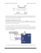
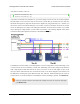
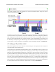
will need to connect an external AND gate. The TX line of each Tic should be connected to an input
line of the AND gate. The output of the AND gate should be connected to the RX line of your serial
device (through a voltage divider or level shifter if necessary). The following diagram shows these
connections along with optional connections of the ERR and RST pins:
The ERR pins can all be safely connected together. In such a configuration, the line will be high if one
or more Tics has an error; otherwise, it will be low. Additionally, the Tics are configured by default to
treat a high signal on their ERR lines as an error, so an error on one Tic will trigger an error on all
other Tics when their ERR lines are connected as shown in the above diagram. This behavior can
be disabled by checking the “Ignore ERR line high” box under the “Advanced settings” tab of the Tic
Control Center. For more information on the ERR pin and error handling in general, see Section 5.4.
Using I²C instead of serial to read data from multiple Tics does not require an AND gate
(see Section 4.6).
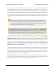
1
2
TicSerial tic1(ticSerial, 14);
TicSerial tic2(ticSerial, 15);
?
Tic Stepper Motor Controller User’s Guide © 2001–2018 Pololu Corporation
4. Setting up the controller Page 36 of 150