
Data Sheet


forth. If the stepper motor is not moving, you should check all of your connections and solder joints (if
applicable). You should check the “Status” tab of the Tic Control Center to see if any errors are being
reported. You can also try slowing down your I²C clock speed to something very slow like 1 kHz or
10 kHz. If slowing down the clock works, then the problem might be due to not having strong enough
pull-up resistors on the SDA and SCL lines.
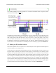
Optional connections
The Tic’s 5V (out) pin provides access to the output of the Tic’s 5V regulator, which also powers
the Tic’s microcontroller and the red and yellow LEDs. You can use the Tic’s regulator to power your
microcontroller or other serial device if the device does not draw too much current (see Section 5.7).
The VM pin provides access to the Tic’s power supply after the reverse-voltage protection circuit, and
this pin can be used to provide reverse-voltage-protected power to other components in the system if
the Tic supply voltage is within the operating range of those components. Note: this pin should not be
used to supply more than 500 mA; higher-current connections should be made directly to the power
supply. Unlike the 5V (out) pin described above, this is not a regulated, logic-level output.
The ERR pin of the Tic is normally pulled low, but drives high to indicate when an error is stopping
the motor. You can connect this line to an input on your microcontroller (assuming it is 5V tolerant) to
quickly tell whether the Tic is experiencing an error or not. Alternatively, you can query the Tic’s serial
interface to see if an error is happening, and which specific errors are happening. For more information
about the ERR pin, see Section 5.4.
The RST pin of the Tic is connected directly to the reset pin of the Tic’s microcontroller and also has
a 10 kΩ resistor pulling it up to 5 V. You can drive this pin low to perform a hard reset of the Tic’s
microcontroller and de-energize the stepper motor, but this should generally not be necessary for
typical applications. You should wait at least 10 ms after a reset to transmit to the Tic.
Controlling multiple Tics with I²C
I²C is designed so that you can control multiple slave devices on a single bus. Before attempting to
do this, however, we recommend that you first get your system working with just one Tic as described
above.
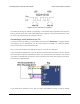
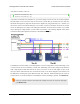
Next, make sure that the I²C master device and the Tics all share a common ground, for example by
connecting a GND pin from the I²C master device to a GND pin on each of the Tics. Make sure that
the SCL pins of all devices are connected and that the SDA pins of all devices are connected.
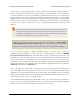
You should use the Tic Control Center to configure each Tic to have a different “Device number”, which
specifies the 7-bit I²C address to use. Then you should change your code to use those addresses. If
you are using our Tic Arduino library, can declare one object for each Tic by writing code like this at
the top of your sketch, which uses addresses 14 and 15:
Tic Stepper Motor Controller User’s Guide © 2001–2018 Pololu Corporation
4. Setting up the controller Page 39 of 150