
Data Sheet


In this mode, the Tic will behave like an electronic speed controller (ESC), except with a stepper motor
instead of a DC motor.
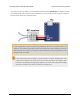
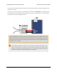
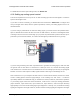
If you have not done so already, you should follow the instructions in Section 4.3 to configure and test
your stepper motor. Next, with the system unpowered, connect your RC receiver to the Tic’s GND, 5V,
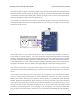
and RC pins as shown in the diagram below.
In this configuration, the RC receiver will be powered by the Tic’s 5 V regulator via the 5V
output pin. If you want to power the receiver from another power source instead, you should
not connect the Tic’s 5V pin to it as doing so would short the two sources together and could
damage the Tic or receiver.
If the Tic gets reset when you plug in your RC receiver, it might be because the in-rush
current of the receiver is too much for the Tic’s 5V line and causes its voltage to drop
temporarily. As general good engineering practice, we recommend making and breaking
electrical connections only while your devices are powered off.
Tic Stepper Motor Controller User’s Guide © 2001–2018 Pololu Corporation
4. Setting up the controller Page 43 of 150