
Data Sheet

UM10204 All information provided in this document is subject to legal disclaimers. © NXP Semiconductors N.V. 2014. All rights reserved.
User manual Rev. 6 — 4 April 2014 13 of 64
NXP Semiconductors
UM10204
I
2
C-bus specification and user manual
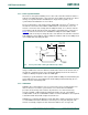
3.1.9 Clock stretching
Clock stretching pauses a transaction by holding the SCL line LOW. The transaction
cannot continue until the line is released HIGH again. Clock stretching is optional and in
fact, most slave devices do not include an SCL driver so they are unable to stretch the
clock.
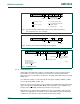
On the byte level, a device may be able to receive bytes of data at a fast rate, but needs
more time to store a received byte or prepare another byte to be transmitted. Slaves can
then hold the SCL line LOW after reception and acknowledgment of a byte to force the
master into a wait state until the slave is ready for the next byte transfer in a type of
handshake procedure (see Figure 7
).
On the bit level, a device such as a microcontroller with or without limited hardware for the
I
2
C-bus, can slow down the bus clock by extending each clock LOW period. The speed of
any master is adapted to the internal operating rate of this device.
In Hs-mode, this handshake feature can only be used on byte level (see Section 5.3.2
).
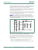
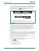
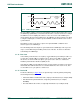
3.1.10 The slave address and R/W bit
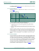
Data transfers follow the format shown in Figure 9. After the START condition (S), a slave
address is sent. This address is seven bits long followed by an eighth bit which is a data
direction bit (R/W
) — a ‘zero’ indicates a transmission (WRITE), a ‘one’ indicates a
request for data (READ) (refer to Figure 10
). A data transfer is always terminated by a
STOP condition (P) generated by the master. However, if a master still wishes to
communicate on the bus, it can generate a repeated START condition (Sr) and address
another slave without first generating a STOP condition. Various combinations of
read/write formats are then possible within such a transfer.
Fig 9. A complete data transfer
S
1 - 7 8 9 1 - 7 8 9 1 - 7 8 9
P
STOP
condition
START
condition
DATA ACKDATA ACKADDRESS ACKR/W
SDA
SCL
mbc604
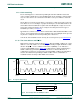
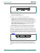
Fig 10. The first byte after the START procedure
mbc608
R/W
LSBMSB
slave address