
Data Sheet

UM10204 All information provided in this document is subject to legal disclaimers. © NXP Semiconductors N.V. 2014. All rights reserved.
User manual Rev. 6 — 4 April 2014 16 of 64
NXP Semiconductors
UM10204
I
2
C-bus specification and user manual
All combinations of read/write formats previously described for 7-bit addressing are
possible with 10-bit addressing. Two are detailed here:
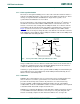
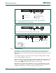
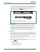
• Master-transmitter transmits to slave-receiver with a 10-bit slave address.
The transfer direction is not changed (see Figure 14
). When a 10-bit address follows
a START condition, each slave compares the first seven bits of the first byte of the
slave address (1111 0XX) with its own address and tests if the eighth bit (R/W
direction bit) is 0. It is possible that more than one device finds a match and generate
an acknowledge (A1). All slaves that found a match compare the eight bits of the
second byte of the slave address (XXXX XXXX) with their own addresses, but only
one slave finds a match and generates an acknowledge (A2). The matching slave
remains addressed by the master until it receives a STOP condition (P) or a repeated
START condition (Sr) followed by a different slave address.
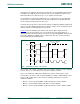
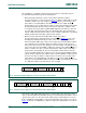
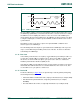
• Master-receiver reads slave-transmitter with a 10-bit slave address.
The transfer direction is changed after the second R/W
bit (Figure 15). Up to and
including acknowledge bit A2, the procedure is the same as that described for a
master-transmitter addressing a slave-receiver. After the repeated START condition
(Sr), a matching slave remembers that it was addressed before. This slave then
checks if the first seven bits of the first byte of the slave address following Sr are the
same as they were after the START condition (S), and tests if the eighth (R/W
) bit is 1.
If there is a match, the slave considers that it has been addressed as a transmitter
and generates acknowledge A3. The slave-transmitter remains addressed until it
receives a STOP condition (P) or until it receives another repeated START condition
(Sr) followed by a different slave address. After a repeated START condition (Sr), all
the other slave devices will also compare the first seven bits of the first byte of the
slave address (1111 0XX) with their own addresses and test the eighth (R/W
) bit.
However, none of them will be addressed because R/W
= 1 (for 10-bit devices), or the
1111 0XX slave address (for 7-bit devices) does not match.
Slave devices with 10-bit addressing react to a ‘general call’ in the same way as slave
devices with 7-bit addressing. Hardware masters can transmit their 10-bit address after a
‘general call’. In this case, the ‘general call’ address byte is followed by two successive
bytes containing the 10-bit address of the master-transmitter. The format is as shown in
Figure 15
where the first DATA byte contains the eight least-significant bits of the master
address.
Fig 14. A master-transmitter addresses a slave-receiver with a 10-bit address
mbc613
R/W
A1
(write)
A2
A
A/A
1 1 1 1 0 X X 0
SLAVE ADDRESS
1st 7 BITS
S DATA PDATA
SLAVE ADDRESS
2nd BYTE
Fig 15. A master-receiver addresses a slave-transmitter with a 10-bit address
mbc614
R/W A1
(write)
A3 DATA DATAA2 R/W
(read)
1 1 1 1 0 X X 0 1 1 1 1 0 X X 1
A
APSr
SLAVE ADDRESS
1st 7 BITS
SLAVE ADDRESS
2nd BYTE
SLAVE ADDRESS
1st 7 BITS
S