
Data Sheet

UM10204 All information provided in this document is subject to legal disclaimers. © NXP Semiconductors N.V. 2014. All rights reserved.
User manual Rev. 6 — 4 April 2014 18 of 64
NXP Semiconductors
UM10204
I
2
C-bus specification and user manual
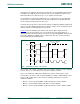
There are two cases to consider:
• When the least significant bit B is a ‘zero’.
• When the least significant bit B is a ‘one’.
When bit B is a ‘zero’, the second byte has the following definition:
• 0000 0110 (06h): Reset and write programmable part of slave address by
hardware. On receiving this 2-byte sequence, all devices designed to respond to the
general call address reset and take in the programmable part of their address.
Precautions must be taken to ensure that a device is not pulling down the SDA or SCL
line after applying the supply voltage, since these low levels would block the bus.
• 0000 0100 (04h): Write programmable part of slave address by hardware.
Behaves as above, but the device does not reset.
• 0000 0000 (00h): This code is not allowed to be used as the second byte.
Sequences of programming procedure are published in the appropriate device data
sheets. The remaining codes have not been fixed and devices must ignore them.
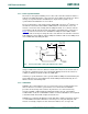
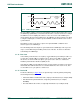
When bit B is a ‘one’, the 2-byte sequence is a ‘hardware general call’. This means that
the sequence is transmitted by a hardware master device, such as a keyboard scanner,
which can be programmed to transmit a desired slave address. Since a hardware master
does not know in advance to which device the message has to be transferred, it can only
generate this hardware general call and its own address — identifying itself to the system
(see Figure 17
).
The seven bits remaining in the second byte contain the address of the hardware master.
This address is recognized by an intelligent device (for example, a microcontroller)
connected to the bus which then accepts the information from the hardware master. If the
hardware master can also act as a slave, the slave address is identical to the master
address.
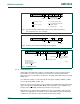
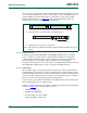
Fig 16. General call address format
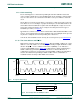
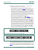
Fig 17. Data transfer from a hardware master-transmitter
mbc623
LSB
second byte
0 0 0 0 0 0 0 0 A X X X X X X X BA
first byte
(general call address)
mbc624
general
call address
(B)
A A
second
byte
A A
(n bytes + ack.)
S 00000000 MASTER ADDRESS 1 PDATA DATA