
Data Sheet

UM10204 All information provided in this document is subject to legal disclaimers. © NXP Semiconductors N.V. 2014. All rights reserved.
User manual Rev. 6 — 4 April 2014 40 of 64
NXP Semiconductors
UM10204
I
2
C-bus specification and user manual
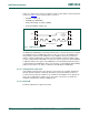
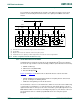
5.3.3 Switching from F/S-mode to Hs-mode and back
After reset and initialization, Hs-mode devices must be in Fast-mode (which is in effect
F/S-mode, as Fast-mode is downward compatible with Standard-mode). Each Hs-mode
device can switch from Fast-mode to Hs-mode and back and is controlled by the serial
transfer on the I
2
C-bus.
Before time t
1
in Figure 34, each connected device operates in Fast-mode. Between times
t
1
and t
H
(this time interval can be stretched by any device) each connected device must
recognize the ‘S 00001XXX A’ sequence and has to switch its internal circuit from the
Fast-mode setting to the Hs-mode setting. Between times t
1
and t
H
, the connected master
and slave devices perform this switching by the following actions.
The active (winning) master:
1. Adapts its SDAH and SCLH input filters according to the spike suppression
requirement in Hs-mode.
2. Adapts the set-up and hold times according to the Hs-mode requirements.
3. Adapts the slope control of its SDAH and SCLH output stages according to the
Hs-mode requirement.
4. Switches to the Hs-mode bit-rate, which is required after time t
H
.
5. Enables the current source pull-up circuit of its SCLH output stage at time t
H
.
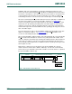
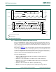
Fig 34. A complete Hs-mode transfer
msc618
8-bit master code 0000 1xxx
A
t
H
t
1
S
F/S mode
HS mode
If P then
F/S mode
If Sr (dotted lines)
then HS mode
16789 67891
1 2 to 5
2 to 5
2 to 5
67 89
SDA high
SCL high
SDA high
SCL high
t
H
t
FS
Sr Sr P
n + (8-bit data + A/A)
7-bit SLA
R/W A
= Master current source pull-up
= Resistor pull-up