UM2356 User manual VL53L1X API user manual Introduction The VL53L1X is a long distance ranging Time-of-Flight sensor. The purpose of this user manual is to describe the set of functions to call to get ranging data using the VL53L1X driver. Please refer to the VL53L1X datasheet. Figure 1. VL53L1X ranging sensor module March 2018 DocID031478 Rev 1 1/28 www.st.
Contents UM2356 Contents 1 VL53L1X system overview . . . . . . . . . . . . . . . . . . . . . . . . . . . . . . . . . . . . 4 2 Ranging API function descriptions . . . . . . . . . . . . . . . . . . . . . . . . . . . . . 5 2.1 Autonomous ranging description . . . . . . . . . . . . . . . . . . . . . . . . . . . . . . . . 5 2.2 Timing considerations . . . . . . . . . . . . . . . . . . . . . . . . . . . . . . . . . . . . . . . . 5 2.3 API function call flows . . . . . . . . . . . . . . . . . . . . . .
UM2356 Contents 3.2 3.3 Offset calibration . . . . . . . . . . . . . . . . . . . . . . . . . . . . . . . . . . . . . . . . . . . 20 3.2.1 Offset calibration function . . . . . . . . . . . . . . . . . . . . . . . . . . . . . . . . . . . 20 3.2.2 Offset calibration procedure . . . . . . . . . . . . . . . . . . . . . . . . . . . . . . . . . . 20 3.2.3 Getting offset calibration results . . . . . . . . . . . . . . . . . . . . . . . . . . . . . . . 20 3.2.4 Setting offset calibration data . . . . . .
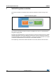
VL53L1X system overview 1 UM2356 VL53L1X system overview The VL53L1X system is composed of the VL53L1X module and a driver running on the host. Figure 2. VL53L1X system ,ŽƐƚ ŽƐƚ s>ϱϯ>ϭy ^LJƐƚĞŵ s>ϱϯ>ϭy ƌŝǀĞƌ /Ϯ s>ϱϯ>ϭy ŵŽĚƵůĞ ST delivers a software driver, referred to as the “driver” in this document. This document describes the driver functions accessible to the host, to control the device and get the ranging data.
UM2356 Ranging API function descriptions 2 Ranging API function descriptions This section give a functional description of the ranging and describes the API call flow that should be followed to perform a ranging measurement using the VL53L1X. 2.1 Autonomous ranging description The sensor performs the ranging continuously and autonomously with a programmable inter-measurement period. Ranging is done without involvement from the host which allows the host to be in a lowpower state.
Ranging API function descriptions 2.3 UM2356 API function call flows The VL53L1X driver is used in two use cases: 2.3.1 • Calibration flow for device calibration • Ranging flow used at user applications level Calibration flow Calibration flow is described in Figure 4. All API functions for calibration are described in Section 3: Calibration functions. Figure 4.
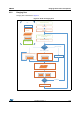
UM2356 2.3.2 Ranging API function descriptions Ranging flow Ranging flow is described in Figure 5. Figure 5.
Ranging API function descriptions 2.4 UM2356 Mandatory ranging functions The following sections shows the API functions required to perform system initialization, before starting a measurement. 2.4.1 Data init The VL53L1_DataInit() function is called once. It performs device initialization. It is called once and only once after the device is brought out of reset. 2.4.2 Static Init The VL53L1_StaticInit() function allows loading of the device settings that are specific for a given use case. 2.4.
UM2356 2.4.6 Ranging API function descriptions Clear source of interrupt The interrupt must be cleared by calling the driver function: VL53L1_ClearInterruptAndStartMeasurement()after reading the ranging data To get consistent results, it is mandatory to call this function after getting the ranging measurement. If this function is not called, the next ranging will start and the results will be updated. But, the data ready status flag will not be updated, and the physical interrupt pin will not be cleared.
Ranging API function descriptions UM2356 Example: Status = VL53L1_SetInterMeasurementPeriodMilliSeconds(&VL53L1Dev, 1000 ); sets the inter-measurement period to 1 s. The function VL53L1_GetInterMeasurementPeriodMilliSeconds() gets the programmed inter-measurement period. Note: If the inter-measurement period is shorter than the timing budget, once the device completes the ranging, the next ranging starts immediately.
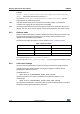
UM2356 Ranging API function descriptions Table 2 gives the default limit states and values. Table 2. Default limit states and values Limit ID Default limit state Default limit value Associated RangeStatus Sigma Enabled 15 mm 1 Signal Enabled 1 Mcps 2 If the user disables the limit checks, the ranging values will no longer be filtered and an incorrect measurement could be returned by the sensor. In this case, RangeStatus 1 and 2 will never be reported.
Ranging API function descriptions 2.5.5 UM2356 Thresholds The device can be configured to operate in distance and/or signal threshold detection mode. The ranging data is reported to the host when the pre-configured criteria are matched.
UM2356 Ranging API function descriptions Example: Detectionconfig.DetectionMode = 1 Detectionconfig.Distance.CrossMode = 3 Detectionconfig.IntrNoTarget = 0 Detectionconfig.Distance.High = 1000 Detectionconfig.Distance.Low = 100 Status = VL53L1_SetThresholdConfig(&VL53L1Dev, &detectionConfig ); This function is used to program the device to report ranging only when an object is detected within 10 cm and 1 m (as in this example).
Ranging API function descriptions UM2356 7RS/HIW< %RW5LJKW< Ϭ ϭ Ϯ ϯ ϰ ϱ ϲ ϳ ϴ ϵ ϭϬ ϭϭ ϭϮ ϭϯ ϭϰ ϭϱ ϭϬ z y/^ Figure 6.
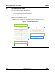
UM2356 2.5.7 Ranging API function descriptions Spad array coordinates versus scene Figure 7 shows the coordinates of an object in the SPAD array compared to the location in the FoV. Figure 7. VL53L1X coordinates vs scene 2.5.8 Optical center coordinates Due to assembly tolerances, the optical center of the device can vary. The optical center of the device is measured for each part. The optical center coordinates are stored in the device NVM.
Ranging API function descriptions 2.5.9 UM2356 VDDIO configuration As described in the datasheet, the user can select two modes for a VDDIO value of 1V8 or 2V8 modes. The selection of the mode is made directly in the code though a compilation key called USE_I2C_2V8k. If this compilation key is defined, the system will go into 2V8 mode, otherwise, it will be kept in the default 1V8 mode. 2.
UM2356 Ranging API function descriptions Table 4.
Calibration functions 3 UM2356 Calibration functions To benefit from the full performance of the device, the VL53L1X driver includes calibration functions that should be run once at the customer production line. Calibration procedures have to be run to compensate the part-to-part parameters and the presence of the cover glass that may affect the device performance. Calibration data stored in the host have to be loaded into theVL53L1X at each startup using a dedicated driver function.
UM2356 3.1.2 Calibration functions RefSPAD calibration procedure The user has to ensure that there are no targets closer than 5 cm from the sensor during the calibration. It is better to perform this calibration in low IR light conditions (indoor). The time to perform this calibration is only few milliseconds. The VL53L1_PerformRefSpadManagement function has to be called after the VL53L1_DataInit() and VL53L1_StaticInit() functions are called. Refer to Figure 4: VL53L1X calibration flow.
Calibration functions 3.2 UM2356 Offset calibration Soldering the device on the customer board or adding a cover glass can introduce an offset in the ranging distance. This part-to-part offset has to be measured and compensated during the offset calibration. 3.2.1 Offset calibration function A dedicated function is available for this operation: VL53L1_PerformOffsetSimpleCalibration(&VL53L1Dev, CalDistanceMilliMeter) The argument of the function is the offset calibration distance in millimeters.
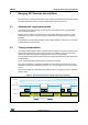
UM2356 3.3 Calibration functions Crosstalk calibration Crosstalk (xtalk) is defined as the amount of the return signal received on the sensing array which is due to VCSEL light reflection inside the protective window (cover glass) added on top of the module for aesthetic and protective reasons. Depending on the cover glass quality, the amount of the return signal can be significant and can affect the sensor performance.
Calibration functions UM2356 Figure 8. VL53L1X crosstalk calibration distance definition ZĂŶŐŝŶŐ ĚŝƐƚĂŶĐĞ /ĚĞĂů ZĂŶŐŝŶŐ ĐƵƌǀĞ ZĂŶŐŝŶŐ ĐƵƌǀĞ ǁŝƚŚ yƚĂůŬ ĐŽŵƉĞŶƐĂƚĞĚ yƚĂůŬ ĐĂůŝďƌĂƚŝŽŶ ĚŝƐƚĂŶĐĞ ZĂŶŐŝŶŐ ĐƵƌǀĞ ǁŝƚŚ yƚĂůŬ ĞĨĨĞĐƚ dĂƌŐĞƚ ĚŝƐƚĂŶĐĞ The crosstalk calibration distance corresponds to the maximum ranging distance achievable reported by the sensor when the cover glass is present (see Figure 8). This maximum ranging distance is one argument of the crosstalk calibration driver function.
UM2356 3.3.6 Calibration functions Enable/Disable crosstalk compensation The function to call to enable or disable the crosstalk compensation is: VL53L1_SetXTalkCompensationEnable(). VL53L1_SetXTalkCompensationEnable(&VL53L1Dev, 0); // disables the crosstalk compensation. V53L1_SetXTalkCompensationEnable(&VL53L1Dev, 1); // enables the crosstalk compensation. Note: This function does not perform any crosstalk calibration or data loading, it just enables the crosstalk compensation.
Driver errors and warnings 4 UM2356 Driver errors and warnings The driver error is reported when any driver function is called. Possible values for driver errors are described in Table 7. Please note that warnings exist to inform the user that some parameters are not optimized. The warnings are not blocking points for the host. Table 7.
UM2356 Driver errors and warnings Table 7. Bare driver errors and warnings descriptions (continued) Error value API error string Occurrence -31 VL53L1_WARNING_OFFSET_CAL_MISSING_ SAMPLES Thrown if there is less than the requested number of valid samples. Ensure offset calibration setup is in line with ST recommendations. -32 VL53L1_WARNING_OFFSET_CAL_SIGMA_ TOO_HIGH Thrown if the offset calibration range sigma estimate is too high.
Acronyms and abbreviations 5 UM2356 Acronyms and abbreviations Table 8.
UM2356 6 Revision history Revision history Table 9.
UM2356 IMPORTANT NOTICE – PLEASE READ CAREFULLY STMicroelectronics NV and its subsidiaries (“ST”) reserve the right to make changes, corrections, enhancements, modifications, and improvements to ST products and/or to this document at any time without notice. Purchasers should obtain the latest relevant information on ST products before placing orders. ST products are sold pursuant to ST’s terms and conditions of sale in place at the time of order acknowledgement.