Pololu Wixel User's Guide © 2001–2014 Pololu Corporation Pololu Wixel User's Guide http://www.pololu.
Pololu Wixel User's Guide © 2001–2014 Pololu Corporation 1. Overview . . . . . . . . . . . . . . . . . . . . . . . . . . . . . . . . . . . . . 1.a. Module Pinout and Components . . . . . . . . . . . . . . . . . . . . . 1.b. Supported Operating Systems . . . . . . . . . . . . . . . . . . . . . . . 1.c. Government Regulations for Radio Devices . . . . . . . . . . . . . . . 2. Contacting Pololu . . . . . . . . . . . . . . . . . . . . . . . . . . . . . . . . . 3. Getting Started . . . . . . . . . . . . . . .
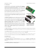
Pololu Wixel User's Guide © 2001–2014 Pololu Corporation 1. Overview The Pololu Wixel is a general-purpose programmable module featuring a 2.4 GHz radio and USB. The Wixel is based around the CC2511F32 [http://focus.ti.com/docs/prod/folders/print/cc2511f32.html] microcontroller from Texas Instruments, which has an integrated radio transceiver, 32 KB of flash memory, 4 KB of RAM, and a full-speed USB interface. A total of 15 general-purpose I/O lines are available, including 6 analog inputs, and the 0.
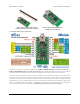
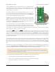
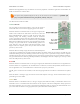
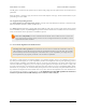
Pololu Wixel User's Guide Wixel programmable USB wireless module (without header pins installed). © 2001–2014 Pololu Corporation Wixel programmable USB wireless module (fully assembled). 1.a. Module Pinout and Components The Wixel can connect to a computer’s USB port via a USB A to Mini-B cable [http://www.pololu.com/product/130] or a USB A to Mini-B adapter [http://www.pololu.com/product/1126] (not included). The USB connection is used to configure the Wixel and also to transmit and receive data.
Pololu Wixel User's Guide © 2001–2014 Pololu Corporation The three GND pins are all connected and are at 0 V by definition. When connecting the Wixel to other electronic systems, you should make sure that the Wixel’s GND is connected to the other system’s GND unless you are doing something very advanced. The Wixel can be powered from VIN pin. Simply connect a 2.7–6.5 V power source between VIN and GND, with the positive terminal going to VIN. It is OK to connect VIN and USB at the same time.
Pololu Wixel User's Guide © 2001–2014 Pololu Corporation Different Wixel applications may use different sets of these peripherals. Consult the application documentation for details on the behavior of the I/O lines. The pinout and peripheral diagram at the top of this section is also available as a printable pdf [http://www.pololu.com/file/download/wixel_pinout.pdf?file_id=0J462] (145k pdf).
Pololu Wixel User's Guide © 2001–2014 Pololu Corporation The P2_2 pin is connected to the yellow LED, so this line will go high when the yellow LED is on and otherwise be pulled low. While the Wixel is running its app, the behavior of this LED depends on the app. See the documentation of your particular app for more details. 1.b.
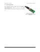
Pololu Wixel User's Guide © 2001–2014 Pololu Corporation 2. Contacting Pololu We would be delighted to hear from you about any of your projects and about your experience with the Wixel. You can contact us [http://www.pololu.com/contact] directly or post on our forum [http://forum.pololu.com/]. Tell us what we did well, what we could improve, what you would like to see in the future, or anything else you would like to say! Wixel programmable USB wireless module with USB cabled connected. 2.
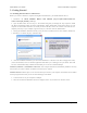
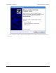
Pololu Wixel User's Guide © 2001–2014 Pololu Corporation 3. Getting Started 3.a. Installing Windows Drivers and Software Before you connect a Wixel to a computer running Microsoft Windows, you should install the drivers: 1. Download the Wixel windows-121129.zip?file_id=0J448] Windows Drivers (12MB zip) and Software [http://www.pololu.com/file/download/wixel- 2. Open the ZIP archive and run setup.exe.
Pololu Wixel User's Guide © 2001–2014 Pololu Corporation 7. On the second screen of the “Found New Hardware Wizard”, select “Install the software automatically” and click “Next”. 3.
Pololu Wixel User's Guide © 2001–2014 Pololu Corporation 8. Windows XP will warn you again that the driver has not been tested by Microsoft and recommend that you stop the installation. Click “Continue Anyway”. 9. When you have finished the “Found New Hardware Wizard”, click “Finish”. 3.
Pololu Wixel User's Guide © 2001–2014 Pololu Corporation After installing the drivers, if you go to your computer’s Device Manager and expand the “Pololu USB Devices” list, you should see an entry for the Pololu Wixel USB Bootloader. Windows Vista or Windows 7 Device Manager showing a Wixel in bootloader mode. Windows XP Device Manager showing a Wixel in bootloader mode. If you see the “Pololu Wixel USB Bootloader” entry in your device manager, it means that your Wixel is in bootloader mode.
Pololu Wixel User's Guide Windows Vista or Windows 7 Device Manager showing a Wixel that is running an app with a virtual COM port. © 2001–2014 Pololu Corporation Windows XP Device Manager showing a Wixel that is running an app with a virtual COM port. In parentheses, you will see the name of the port (for example, COM5 or COM6). Some software will not allow connection to higher COM port numbers. If you need to change the COM port number assigned to a Wixel, you can do so using the Device Manager.
Pololu Wixel User's Guide © 2001–2014 Pololu Corporation 3.b. Installing Linux Drivers and Software The Wixel Configuration Utility running in Ubuntu Linux. You can download the Wixel Configuration Utility and the Wixel command-line utility (wixelcmd) for Linux here: • Wixel Linux Software for (211k gz) i386 (32-bit) [http://www.pololu.com/file/download/wixel- (64-bit) [http://www.pololu.com/file/download/wixel- linux-110623-i386.tar.
Pololu Wixel User's Guide © 2001–2014 Pololu Corporation depends on how many other ACM devices you have plugged in). You can use any terminal program (such as kermit or screen) to send and receive bytes on those ports. 3.c. Installing Mac OS X Drivers and Software Mac OS X compatibility: we have confirmed that the Wixel works on Mac OS X 10.7 and we can assist with advanced technical issues, but most of our tech support staff does not use Macs, so basic support for Mac OS X is limited.
Pololu Wixel User's Guide © 2001–2014 Pololu Corporation 3.d. Loading an Example App When you first get your Wixel it will have no application loaded. To make your Wixel do something useful, you must load an app onto it. This section guides you through the steps needed to load an example application onto the Wixel using the Wixel Configuration Utility. 1. Install the Wixel drivers and software by following the instructions in the preceding sections. 2.
Pololu Wixel User's Guide © 2001–2014 Pololu Corporation The Wixel Configuration Utility with the Example Blink LED App open. 5. Note that in the Wixels box, there is a list of all the Wixels connected to USB that the Wixel Configuration Utility can recognize. There is one Wixel connected, and its 32-bit serial number is displayed in the list. Also note that in the App Configuration box, we have opened the example_blink_led_v1.0.wxl app.
Pololu Wixel User's Guide © 2001–2014 Pololu Corporation 9. The speed of the blinking is determined by the blink_period_ms parameter. The units of this parameter are milliseconds (ms). Try changing blink_period_ms to 100 by double-clicking on the number and typing “100”. You can now write the new configuration to the Wixel by clicking the “Write to Wixel” button. After the writing is done and the app is running, you should see the red LED blinking 5 times faster than it was before. 10.
Pololu Wixel User's Guide © 2001–2014 Pololu Corporation Serial App [http://www.pololu.com/docs/0J46/9.b], the only thing that will be different are the names and meanings of the parameters. To understand what the different parameters mean, refer to the documentation for your specific app. Some apps might implement a non-standard USB interface (or no USB interface at all).
Pololu Wixel User's Guide © 2001–2014 Pololu Corporation 4. Configuring Your Wixels The Wixel Configuration Utility allows you to write and read settings from the Wixel. This section explains all of the features of the Wixel Configuration Utility in detail. The Wixel Configuration Utility with 2 Wixels connected and an App file open.
Pololu Wixel User's Guide © 2001–2014 Pololu Corporation The text displayed in the Wixel list (e.g. “07-C2-C8-3A”) is the serial number of your Wixel. Each Wixel has a unique 32-bit serial number which was randomly generated and assigned to it when the Wixel was manufactured. The icon displayed in the Wixel list represents the current state of the Wixel. Each Wixel will be in one of these states: Wixel Status Icon Description App Running The app you loaded on the Wixel is now running.
Pololu Wixel User's Guide © 2001–2014 Pololu Corporation Wixels (for example, when you want to write the same app and settings to multiple Wixels). If the box is unchecked, you can click the Read Wixel button at any time to read settings from the selected Wixel. To read the settings from a Wixel, you will need to open the app that is currently on the Wixel.
Pololu Wixel User's Guide © 2001–2014 Pololu Corporation 5. Connecting Your Wixels This chapter explains some of the electrical connections you might need to make to get your Wixel working the way you want it to. 5.a. Connecting Power The two main ways of powering the Wixel are the USB port and the VIN pin. The schematic of the Wixel’s power system is shown below: Wixel power system schematic diagram. VIN Power Input The Wixel can be powered from VIN if you connect a 2.7–6.5 V power supply (e.g.
Pololu Wixel User's Guide © 2001–2014 Pololu Corporation The Wixel can be powered from USB. 3V3 Power Output The Wixel’s 3V3 pin gives access to the output of the Wixel’s 3.3 V regulator. If the Wixel’s power supply drops below approximately 3.5 V, the 3V3 output will be less than 3.3 V. Normally this output can provide up to 150 mA, but if the Wixel’s power supply is above 5 V then it is limited to 100 mA. You can use 3V3 to power your own 3.3 V devices.
Pololu Wixel User's Guide Making serial connections between a Wixel and a 5V microcontroller. © 2001–2014 Pololu Corporation Making serial connections between a Wixel and a 3.3V microcontroller. To connect your microcontroller to a Wixel for serial communication, make these connections: • GND: Connect the ground (also known as GND or VSS) of your microcontroller to one of the GND pins on the Wixel. This connection is required.
Pololu Wixel User's Guide © 2001–2014 Pololu Corporation • You loaded a program which uses a different type of USB interface or no USB interface. In this case, check the documentation of the app to see if there is a convenient way for getting the Wixel into bootloader mode. No matter what state the Wixel is in, you can manually get it into bootloader mode by connecting USB, setting P2_2 high, and resetting the Wixel. There are two main ways to accomplish this.
Pololu Wixel User's Guide © 2001–2014 Pololu Corporation Wixel on breadboard with a bootloader button and reset button connected. 5.
Pololu Wixel User's Guide © 2001–2014 Pololu Corporation 6. Using a Virtual COM Port Most of the available Wixel apps implement a USB interface that consists of a single virtual COM (serial) port. This interface allows you to send and receive bytes from the Wixel in the same way you would send and receive bytes from any other serial port on your computer. 6.a. Determining the Port Name To connect to a COM port, you usually have to know the name of the port.
Pololu Wixel User's Guide © 2001–2014 Pololu Corporation PuTTY is a free Windows terminal program that can send and receive bytes on a serial port. If you need to send and receive non-ASCII bytes, you can use the Pololu Serial Transmitter Utility for Windows [http://www.pololu.com/docs/0J23] or Br@y Terminal. 6.c. Writing PC Software to Use a Serial Port You can write your own computer program that communicates with a serial port. The freely available Microsoft .
Pololu Wixel User's Guide © 2001–2014 Pololu Corporation 7. Ensuring a Good Radio Signal Here are some tips for improving the quality of the radio signals sent between a pair of Wixels: • Reduce the distance between the Wixels, if possible. • Try different frequencies. Most Wixel apps that use the radio have a radio_channel parameter that determines what frequency will be used. By switching to a different channel you might be able to avoid interference from other nearby 2.4 GHz radios.
Pololu Wixel User's Guide © 2001–2014 Pololu Corporation 8. Schematic Diagram The schematic diagram of the Wixel is shown below: The schematic also available as (51k pdf). a printable pdf [http://www.pololu.com/file/download/ wixel_schematic.pdf?file_id=0J463] 8.
Pololu Wixel User's Guide © 2001–2014 Pololu Corporation 9. Wixel Apps This section describes some of the available Wixel apps written by Pololu; you can find their source code in the Wixel SDK (see Section 10). For more apps, including ones written by community members, see the Wixel SDK and the Wixel Apps forum thread [http://forum.pololu.com/viewtopic.php?f=30&t=5165]. 9.a. Example App: Blink LED This is an example app that blinks the red LED with a configurable period. See Section 3.
Pololu Wixel User's Guide © 2001–2014 Pololu Corporation Default Pinout Pin Function P1_0 DTR general-purpose output pin P1_1 RTS general-purpose output pin P1_2 DSR general-purpose input pin P1_3 CD general-purpose input pin P1_5 PA_PD radio transmit debug output P1_6 TX transmits serial data (0–3.3 V) P1_7 RX receives serial data (0–3.
Pololu Wixel User's Guide © 2001–2014 Pololu Corporation Indicator LEDs The green LED behaves as described in Section 1.a, and also flickers when there is data transferred over USB. The yellow LED represents the state of the radio. If the Wixel is in a serial mode where the radio is not used, the yellow LED will be off.
Pololu Wixel User's Guide © 2001–2014 Pololu Corporation • baud_rate: The baud rate to use for the UART, in bits per second. The default is 9600. We recommend not exceeding 115200. This parameter has no effect on serial communication over the virtual COM port (USB). • radio_channel: The channel number is from 0 to 255 and determines which frequency to broadcast on. The default is 128. Wixels must be on the same channel to communicate with each other.
Pololu Wixel User's Guide © 2001–2014 Pololu Corporation Caveats Data will be lost if the Wixel receives bytes on the RX line faster than the radio can convey them to the other Wixel. If you have trouble, try reducing the amount of data sent to the RX line by lowering the baud rate or adding delays to your microcontroller’s code. Caution: The Wixel’s I/O lines are not 5V tolerant. You must use level-shifters, diodes, or voltage dividers to connect the Wixel to outputs from 5V systems.
Pololu Wixel User's Guide © 2001–2014 Pololu Corporation 9.c. USB-to-Serial App Overview This app allows you to turn a Wixel into a USB-to-TTL serial adapter capable of baud rates up to 350,000 bps. While this app does not use the radio, it has more features than the USB-to-UART mode of the Wireless Serial App (see Section 9.b). Installation Instructions Download the USB-to-Serial App (v1.0) [http://www.pololu.com/file/ download/usb-serial-v1.0.wxl?file_id=0J464] (13k wxl).
Pololu Wixel User's Guide © 2001–2014 Pololu Corporation This app will discard bytes received on the RX line that have framing errors or parity errors, and it will also throw out bytes if there is an RX buffer overrun. An RX buffer overrun should not happen if you are using a baud rate of 350,000 bps or less. Example Uses • The TX line can be used to send commands to a microcontroller or other serial device. • The RX line can be used to receive data from a microcontroller or other serial device.
Pololu Wixel User's Guide © 2001–2014 Pololu Corporation Pinout Pin Function P0_3 ASCII_TX Serial output, transmits ASCII (0–3.3 V) P0_2 ASCII_RX Serial input, receives ASCII (0–3.3 V, not 5 V tolerant) P1_6 BINARY_TX Serial output, transmits arbitrary bytes (0–3.3 V) P1_7 BINARY_RX Serial input, receives arbitrary bytes (0–3.3 V, not 5 V tolerant) ASCII-to-Binary conversion ASCII characters are received on the ASCII_RX pin, converted into the appropriate bytes, and then transmitted on BINARY_TX.
Pololu Wixel User's Guide © 2001–2014 Pololu Corporation Caveats • If data is received on the ASCII_RX or BINARY_RX pins too quickly, it could result in the internal buffers filling up and data loss. This app has 512 bytes of buffer space for the ASCII-to-binary conversion and 512 bytes of buffer space for the binary-to-ASCII conversion. Caution: The Wixel’s I/O lines are not 5V tolerant. You must use level-shifters, diodes, or voltage dividers to connect the Wixel to outputs from 5V systems.
Pololu Wixel User's Guide © 2001–2014 Pololu Corporation Description This device appears to the USB host as a Virtual COM Port (with USB product ID 0x2200). If you are using Windows, you should see an entry labeled “Wixel” in your Device Manager in the “Ports (COM & LPT)” category while the app is running. There are three basic bridge modes that can be selected: 0. Radio-to-I²C: Serial commands from the radio are used to control I²C transfers. Data read from the I²C slave is returned to the radio.
Pololu Wixel User's Guide © 2001–2014 Pololu Corporation ‘S’, 0xEE, 2, 0xF4, 0x2E, ‘P’ To read a two-byte value from register 0xF6 on the same device, whose read address would be 0xEF, the following sequence could be issued (the second ‘S’ generates a repeated START): ‘S’, 0xEE, 1, 0xF6, ‘S’, 0xEF, 2, ‘P’ The Wixel would respond with the two data bytes read from the slave. Any invalid or unrecognized command is ignored and causes the Invalid Command error bit to be set.
Pololu Wixel User's Guide © 2001–2014 Pololu Corporation The yellow LED is on when VIN power is detected. The red LED indicates an error condition when lit; it can be reset by issuing a Get Errors command (described above). General Parameters • bridge_mode: Selects the bridge mode (0–2, see list above). The default is 0. • baud_rate: The baud rate to use for the UART, in bits per second. The default is 9600. We recommend not exceeding 115200.
Pololu Wixel User's Guide © 2001–2014 Pololu Corporation Versions • Serial-to-I²C App v1.0 2011-05-03: Initial release. [http://www.pololu.com/file/download/serial-i2c-v1.0.wxl?file_id=0J480] (26k wxl), released 9.f. I/O Repeater App Overview This app allows you to wirelessly extend the reach of your microcontroller’s I/O lines up to 50 feet using two or more Wixels. An input pin on one Wixel can be mapped to an output pin on another Wixel.
Pololu Wixel User's Guide © 2001–2014 Pololu Corporation After you have loaded this app onto a Wixel, the Wixel will appear to the computer as Virtual COM Port (with USB product ID 0x2200). If you are using Windows, you should see an entry labeled “Wixel” in your Device Manager in the “Ports (COM & LPT)” category while this app is running. You can not send or receive data on this COM port. Its only purpose is to let the Wixel Configuration Utility easily get the Wixel into bootloader mode.
Pololu Wixel User's Guide © 2001–2014 Pololu Corporation Caution: The Wixel’s I/O lines are not 5V tolerant. You must use level-shifters, diodes, or voltage dividers to connect the Wixel to outputs from 5V systems. Also, avoid drawing more current from an I/O line than it can provide (see the discussion of P1_0 and P1_1 in Section 1.a). Avoid connecting multiple output pins together. Versions • I/O Repeater App v1.3 [http://www.pololu.com/file/download/io-repeater-v1.3.
Pololu Wixel User's Guide © 2001–2014 Pololu Corporation Default Pinout Wixel pin Input type Joystick function P0_0 X axis P0_1 Y axis P0_2 P0_3 Analog Z axis Rx axis P0_4 Ry axis P0_5 Rz axis P1_2 Button 1 P1_3 Button 2 P1_4 P1_5 Digital Button 3 Button 4 P1_6 Button 5 P1_7 Button 6 Connecting Buttons and Potentiometers The diagrams below show examples of how buttons, switches, and potentiometers can be connected to the Wixel for use with the Joystick App.
Pololu Wixel User's Guide © 2001–2014 Pololu Corporation the app to a Wixel. (See Section 4 for more information on how this is done.) The Wixel should now appear to your computer as a Human Interface Device. If you are using Windows, there should be a new entry called “HID-compliant game controller” in your Device Manager in the “Human Interface Devices” section. The Wixel will also show up as a keyboard and a mouse, but it does not use those interfaces.
Pololu Wixel User's Guide © 2001–2014 Pololu Corporation 9.h. Wireless Tilt Mouse App Overview This app allows you to make a wireless tilt mouse for your computer. By tilting the mouse, you can control the position of the mouse cursor. The mouse also supports two buttons for clicking. This app requires two Wixels: a transmitter and a receiver.
Pololu Wixel User's Guide © 2001–2014 Pololu Corporation Configuration Utility easily get the transmitter Wixel into bootloader mode when the transmitter Wixel is connected to the computer via USB. Download the Wireless Tilt Mouse Receiver App (v1.0) [http://www.pololu.com/file/download/wireless-tilt-mouse-receiverv1.0.wxl?file_id=0J471] (15k wxl). Open it with the Wixel Configuration Utility, choose your settings, and write it to the receiver Wixel.
Pololu Wixel User's Guide © 2001–2014 Pololu Corporation • invert_x: Set to 1 to invert the horizontal movement of the mouse. Default is 0. • invert_y: Set to 1 to invert the vertical movement of the mouse. Default is 0. • speed: A positive number that determines the speed of the mouse. Default is 100. This speed is linearly proportional to this number. Alternative Parts You could replace the battery pack with a single 9 V battery and a step-down regulator that outputs voltage within the Wixel’s 2.7–6.
Pololu Wixel User's Guide © 2001–2014 Pololu Corporation Connecting the Wixel to the ShiftBrite chain The following connections should be made between the Wixel running the ShiftBrite App and the first ShiftBrite in the chain: Wixel ShiftBrite Function P1_4 EI Enable P1_5 CI Clock P1_6 DI Data P1_7 LI Latch GND GND Ground Additionally, the Wixel and ShiftBrites may share the same VIN as long as the voltage requirements for both modules are satisfied.
Pololu Wixel User's Guide © 2001–2014 Pololu Corporation Tips • The yellow LED is normally on, and flickers whenever data is received from the radio, which might be useful for debugging your wireless connection. • You can use wires with pre-crimped terminals [http://www.pololu.com/category/71/wires-with-pre-crimped-terminals] and crimp connector housings [http://www.pololu.com/category/70/crimp-connector-housings] to make a custom cable between the Wixel and the ShiftBrite chain.
Pololu Wixel User's Guide © 2001–2014 Pololu Corporation 10. Writing Your Own Wixel App 10.a. Getting Started in Windows To get started developing your own Wixel Apps using Windows as the development platform, we recommend that you download and install the Pololu Wixel Development Bundle: wixel-dev-bundle-120127.exe [http://www.pololu.com/file/download/wixel-dev-bundle-120127.exe?file_id=0J526] (10MB exe). This bundle contains four things: • Wixel SDK [http://pololu.github.
Pololu Wixel User's Guide © 2001–2014 Pololu Corporation You might get the following error message from make in Windows: make: Interrupt/Exception caught (code = 0xc00000fd, addr = 0x425073) If you get this error, please run “make -v” at a Command Prompt and make sure that you are running GNU Make 3.82-pololu2 [https://github.com/pololu/make]. This version of make is included in the latest Wixel Development Bundle (see Section 10.a).
Pololu Wixel User's Guide © 2001–2014 Pololu Corporation Creating Your Own Apps Now that you know how to compile apps and quickly load them onto the Wixel to test them, you are ready to develop your own Wixel apps. You can either modify one of the existing apps in the SDK or create your own app. To create your own app, simply copy one of the existing app folders and change the name.
Pololu Wixel User's Guide 11. Navigate to the apps/example_blink_led folder and double-click on open the file in the center pane. © 2001–2014 Pololu Corporation example_blink_led.c. This will 12. Make a small change to example_blink_led.c, such as removing a blank line or adding a comment. Save the file by pressing Ctrl+S or by selecting File > Save. 13. Press Ctrl+B or select Project > Build All to rebuild the project.
Pololu Wixel User's Guide © 2001–2014 Pololu Corporation • If you put your text cursor on a function name, variable name, preprocessor macro, or include directive, then you can quickly jump to the place where that item is defined by pressing F3 or by right-clicking and selecting Open Declaration. • Pressing Ctrl+Tab inside a source (.c) file opens up the corresponding header (.h) file, and vice-versa. This is especially useful if you are writing a Wixel library.
Pololu Wixel User's Guide © 2001–2014 Pololu Corporation Hiding Unused Features By default, Eclipse has a large number of toolbar buttons, views (panes), and menu items that are not needed for developing Wixel applications. You can greatly simplify the user interface of Eclipse by hiding those items. To hide unused toolbar and menu commands, select Window > Customize Perspective…. This brings up the “Customize Perspective C/C++” window. Select the “Command Groups Availability” tab.
Pololu Wixel User's Guide © 2001–2014 Pololu Corporation Announcing your app on the Wixel forum When you are ready for the community to try out a version of your app, you may announce it on the Wixel forum [http://forum.pololu.com/viewforum.php?f=30], attaching your WXL file. It is helpful to paste a copy of your description into your post so that we can see what your app is about before downloading it.
Pololu Wixel User's Guide © 2001–2014 Pololu Corporation Initially, you will commit your changes to your local repository, but when you are ready to publish them, you should set up your own repository on GitHub to make them accessible to the community. To do this, sign up for a GitHub account and fork our repository into a repository on your account. Please do this by clicking the “fork” button at the top of our repository [http://github.
Pololu Wixel User's Guide © 2001–2014 Pololu Corporation The hex section The hex section contains an Intel Hex file that specifies the bytes to write to the flash of the Wixel. See the Intel HEX [http://en.wikipedia.org/wiki/Intel_HEX] page on Wikipedia for more information. The flash memory region on the CC2511F32 that is available for Wixel applications consists of addresses 0x400 through 0x77FF (inclusive). Any line of the HEX file that writes to bytes outside of this region will be ignored.
Pololu Wixel User's Guide © 2001–2014 Pololu Corporation 11. The Wixel USB Bootloader The Wixel comes with a USB bootloader that can be used in conjunction with the Wixel Configuration Utility or WixelCmd to upload apps to the Wixel (no external programmer is required). This section documents some technical details of the bootloader and is intended for advanced users. Flash Memory Sections The bootloader occupies the first 1 KiB (1024 bytes) and the last 2 KiB of the CC2511F32’s flash memory.
Pololu Wixel User's Guide © 2001–2014 Pololu Corporation Startup Procedure Every time the Wixel powers on, the bootloader’s startup code runs. This code decides whether to launch the bootloader or the application by using the following procedure: First, it configures the three LED lines to have internal pull-down resistors and disables the internal pull-up and pull-down resistors of the other Port 2 pins. Second, if the application is not valid (first byte is 0xFF), it goes into bootloader mode.