VIEW Certified Configuration Guide Nortel WLAN Security Switch 2300 Series with AP-2330 January 2008 Edition 1725-36082-001 Version F
Configuration Guide Trademark Information Notice Polycom® and the logo designs SpectraLink® LinkPlus Link NetLink SVP Are trademarks and registered trademarks of Polycom, Inc. in the United States of America and various countries. All other trademarks used herein are the property of their respective owners. Polycom, Inc. has prepared this document for use by Polycom personnel and customers.
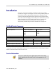
Nortel: WLAN Security Switch 2300 Series with AP-2330 Introduction Polycom’s Voice Interoperability for Enterprise Wireless (VIEW) Certification Program is designed to ensure interoperability and high performance between SpectraLink 8000 Wireless Telephones and wireless LAN (WLAN) infrastructure products. The products listed below have been thoroughly tested in Polycom’s lab and have passed VIEW Certification.
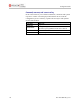
Configuration Guide Contacting Nortel Technical Support If you purchased a service contract for your Nortel product from a distributor or authorized reseller, contact the technical support staff for that distributor or reseller for assistance. Additional information about the Nortel Technical Solutions Centers is available from http://www.nortel.com/contactus. An Express Routing Code (ERC) is available for many Nortel products and services.
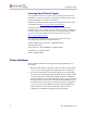
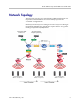
Nortel: WLAN Security Switch 2300 Series with AP-2330 Network Topology The following topology was tested during VIEW Certification. It is important to note that these do not necessarily represent all “Certified” configurations. Both Layer-2 and Layer-3 roaming were tested. Layer-3 roaming of SpectraLink 8000 Wireless Telephones requires the use of a generic routing encapsulation (GRE) tunnel.
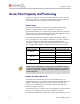
Configuration Guide Access Point Capacity and Positioning Each site is unique in its AP requirements. Therefore, please take the following points into account when determining how many APs are needed and where they should be placed in the facility: Handset range There must be WLAN coverage wherever the SpectraLink 8000 Wireless Telephones will be used.
Nortel: WLAN Security Switch 2300 Series with AP-2330 the available bandwidth per call for 1 Mb/s operation, approximately 10 % of the available bandwidth per call for 2 Mb/s operation, approximately 7 % of the available bandwidth per call for 5.5 Mb/s operation, and approximately 5 % of the available bandwidth per call for 11 Mb/s operations.
Configuration Guide Configuring a New WLAN Security Switch Starting from Factory Defaults 1. Using the supplied DB-9 male to DB-9 female standard RS-232 cable, connect the WLAN Security Switch to the serial port of a terminal or PC. 2. Run a terminal emulation program (such as HyperTerminal) or use a VT-100 terminal with the following configuration: Bits per second: 9600 Data bits: 8 Parity: None Stop bits: 1 Flow control: None 3. Power-on the WLAN Security Switch.
Nortel: WLAN Security Switch 2300 Series with AP-2330 Connecting APs To configure the WLAN Security Switch (WSS) to support an AP, you must first determine how the AP will connect to the switch. There are two types of AP-to-WSS connection: direct and distributed. Directly connected APs In direct connection, an AP connects to one or two 10/100 ports on a WSS. The WSS port is then configured specifically for a direct attachment to an AP.
Configuration Guide Command, comment, and screen text key In the sections below you will find commands, comments and system responses or other screen-displayed information involved in the configuration process. This key explains the text styles and symbols used to denote them.
Nortel: WLAN Security Switch 2300 Series with AP-2330 Configuration Example – CLI AP configuration To add a directly connected AP-2330 attached to port 1 on a WSS using CLI: set port type ap 1 model 2330 poe enable # Defines the port number on the switch that the AP is connected to, the model number of the AP and enables PoE on the switch port. Valid model numbers include the 2330, 2330A and 2330B. set ap 1 radio 1 tx-power 10 mode enable # Sets the channel number, transmit power and enables the 802.
Configuration Guide Service profile / SSID configuration To create a SSID named Voice using WPA-PSK that will be advertised on 802.11a/b/g radios using CLI: set service-profile Voice ssid-name Voice # Creates a new service profile and SSID named Voice. Note it’s a best practice recommendation to use the same name for both the service profile and SSID set service-profile Voice auth-fallthru last-resort # Sets the authentication type to open authentication.
Nortel: WLAN Security Switch 2300 Series with AP-2330 set service-profile Voice auth-dot1x disable # Disables 802.1x authentication. set service-profile Voice attr vlan-name Voice # Specifies the VLAN name to map the voice handsets traffic to. Radio Profile configuration The default Radio Profile needs to be modified to disable certain features to support the handsets.
Configuration Guide # Applies the ACL to the Voice VLAN for ingress and egress traffic. To create an ACL that allows and prioritizes IP protocol 119 (SVP) with a Class of Service (CoS) 7 and denies all other IP traffic on the Voice VLAN using CLI: set security acl ip SpectraLink permit cos 7 119 0.0.0.0 255.255.255.255 0.0.0.0 255.255.255.255 # Creates an ACL that matches protocol 119 (SVP) and marks it with a CoS 7 commit security acl SpectraLink # Commits and applies the ACL.
Nortel: WLAN Security Switch 2300 Series with AP-2330 Configuration Example – WLAN Management Software Adding a WLAN Security Switch to the Network Plan Before WLAN Management Software can be used to configure a WLAN Security Switch, the WSS must be added to the WMS server. To add a WLAN Security Switch to WLAN Management Software: 1. Assuming that WMS is installed and a Network Plan has been created, launch the WMS client and connect to the WMS server.
Configuration Guide 5. In the Enable Password field, type the enable password for the WLAN Security Switch. The enable password must match the enable password that was defined in the Quick Start Wizard. For more information, see the Nortel WLAN Security Switch 2300 Series Configuration Guide. 6. Click the Next button. The uploading progress is shown. 7. After the Successfully uploaded device message is displayed, click the Next button.
Nortel: WLAN Security Switch 2300 Series with AP-2330 5. For directly connected APs, select an available port on the switch from the Available Ports drop-down list. Click the Next button. 6. For distributed APs, enter the Name and Serial Number of the AP. Click the Next button. PN: 1725-36082-001_F.
Configuration Guide 7. Specify the model of the Nortel AP you are configuring. Valid models include 2330, 2330A and 2330B. Click the Next button. 8. To configure the 802.11g Radio: a. Select default for the Radio Profile. b. Specify the Channel Number and Transmit Power the radio should use, as determined by the site survey performed on the facility. Click the Next button. 18 PN: 1725-36082-001_F.
Nortel: WLAN Security Switch 2300 Series with AP-2330 9. To configure the 802.11a Radio, a. Select default for the Radio Profile. b. Specify the Channel Number and Transmit Power the radio should use, as determined by the site survey performed on the facility. 10. Click the Finish button. 11. The AP has now been added to the WLAN Security Switch. PN: 1725-36082-001_F.
Configuration Guide VLAN configuration For security and flexibility it is recommended that voice and data be on separate VLANs. For this example, a new VLAN named Voice with a VLAN ID 2 will be created and tagged to the uplink port 8. 1. In WMS click Configuration on the tool bar. 2. In the Organizer panel, expand the WSS and select VLANs. 3. In the Network Plan Tasks panel, select Create VLAN. 20 PN: 1725-36082-001_F.
Nortel: WLAN Security Switch 2300 Series with AP-2330 4. For VLAN Name enter Voice. 5. For VLAN ID specify 2. Click the Next button. 6. In the Port/Port Group list, select the 802.1Q tagged uplink port (P08) and click the Add button. 7. Click the Tag check box and specify the 802.1Q tag value 2. 8. Click the Finish button. PN: 1725-36082-001_F.
Configuration Guide 9. The Voice VLAN 2 is now 802.1Q tagged to the uplink port P08. a. Highlight the Voice VLAN. b. In the Network Plan Tasks panel, select IGMP. 10. In the VLAN Properties window, disable IGMP by clearing the Enabled check box. Click the OK button. 22 PN: 1725-36082-001_F.
Nortel: WLAN Security Switch 2300 Series with AP-2330 Service Profile / SSID configuration To create a SSID named Voice using WPA-PSK or WPA2-PSK that will be advertised on 802.11a/b/g radios using WMS: 1. In WMS click Configuration on the tool bar. 2. In the Organizer panel expand the WSS and select Wireless Services. 3. In the Network Plan Tasks panel, create a new wireless service by selecting Voice Service Profile. 4. In the New Voice Service Profile introduction screen click the Next button. 5.
Configuration Guide 6. Set the SSID Type to Encrypted and use the default Vendor type SpectraLink. Click the Next button. Selecting the vendor SpectraLink tells WMS what ACLs to create to prioritize the voice traffic later in the wizard. 7. Select the Open Access check box. Click the Next button. MAC authentication may optionally be selected but will require that the MAC addresses for each handset be defined in the local AAA database on the WSS. 24 PN: 1725-36082-001_F.
Nortel: WLAN Security Switch 2300 Series with AP-2330 8. Settings for Wireless Security: a. To support handsets using WPA-PSK security, select the WPA check box. b. To support handsets using WPA2-PSK, select the RSN (WPA2) check box. PN: 1725-36082-001_F.
Configuration Guide 9. Click the Next button. 10. Settings for Wireless Encryption Cipher Suite: a. To support handsets using WPA-PSK with TKIP, select the TKIP check box. 26 PN: 1725-36082-001_F.
Nortel: WLAN Security Switch 2300 Series with AP-2330 b. To support handsets using WPA2-PSK with AES/CCMP, select the AES (CCMP) check box. 11. Click the Next button. PN: 1725-36082-001_F.
Configuration Guide 12. Enter a hexadecimal pre-shared key or passphrase. a. If a passphrase is entered, click the Generate button to generate the hexadecimal pre-shared key. 13. Click the Next button. The pre-shared key must match on both the WSS and handsets or the handsets will not be able to associate with the Voice SSID. 14. Specify the VLAN named Voice. This determines the VLAN that the WSS will map the handset traffic to. Click the Next button. 28 PN: 1725-36082-001_F.
Nortel: WLAN Security Switch 2300 Series with AP-2330 15. A default ACL will be generated which will allow and prioritize IP protocol 119 (SVP) traffic with the Class of Service level 7 and pass all other IP traffic on the Voice VLAN. a. (Optional) Modify the default ACL by removing the last statement, which will allow and prioritize IP protocol 119 (SVP) but deny all other IP traffic on the Voice VLAN. Click the Next button. PN: 1725-36082-001_F.
Configuration Guide 16. Assign the Voice Service Profile to the default Radio Profile. This will determine which 802.11a and 802.11g radios will advertise the Voice SSID. For this example the default Radio Profile will be used which is assigned to all 802.11a/g radios. This will provide support for handsets operating in 802.11a, 802.11b and 802.11g modes. All SpectraLink 8000 Wireless Telephones on the WLAN network must be configured for a single radio standard (802.11a, or 802.11b, or 802.11g).
Nortel: WLAN Security Switch 2300 Series with AP-2330 Radio Profile configuration The default Radio Profile needs to be modified to disable certain features to support the handsets. To modify the default Radio Profile using WMS: 1. In WMS click Configuration on the tool bar. 2. In the Organizer panel expand the WSS and select Radio Profiles. 3. In the Radio Profiles list, highlight the default Radio Profile and click the Properties button. PN: 1725-36082-001_F.
Configuration Guide 4. In the Radio Profile Properties window, click the Radio Profile tab. 5. Clear the Enable Active Scan check box. This disables active scanning, which prevents the radios from going off-channel and disrupting voice services. 32 PN: 1725-36082-001_F.
Nortel: WLAN Security Switch 2300 Series with AP-2330 6. Click the Auto Tune tab. 7. Clear the Tune Channel and Tune Transmit Power check boxes. This disables automatic channel assignment for radios assigned to the radio profile. A static channel configuration is recommended to provide a stable and optimum RF environment for the handsets. PN: 1725-36082-001_F.
Configuration Guide 8. Click the Voice Configuration tab. Verify that the QoS Mode is set to SVP. WMM support is not currently available on the SpectraLink 8000 Wireless Telephones. 9. Click the OK button. 34 PN: 1725-36082-001_F.
Nortel: WLAN Security Switch 2300 Series with AP-2330 Deploying changes Deploying the changes in WMS will upload and save the configuration to the WSS. To deploy the changes in WMS: 1. In WMS click Devices on the tool bar. 2. In the Local Changes Task List panel, select Deploy to upload and save the configuration changes to the WSS. You may also Review, Schedule and Undo changes in the Local Changes Task List panel. PN: 1725-36082-001_F.
Configuration Guide 3. When the Deploy option is selected, WMS will send, apply and save the configuration changes to the WSS. 36 PN: 1725-36082-001_F.
Nortel: WLAN Security Switch 2300 Series with AP-2330 Example Configuration Files (For Reference Only) The following configuration file provides an example configuration to support SpectraLink 8000 Wireless Telephones using WPA-PSK: # Configuration nvgen'd at 2007-7-26 22:51:55 # Image 5.0.11.4.0 # Model 2360 # Last change occurred at 2007-7-26 22:36:12 set ip route default 192.168.1.1 1 set system name WSS2360 set system ip-address 192.168.1.
Configuration Guide set vlan 2 port 8 tag 2 set igmp disable vlan Voice set interface 1 ip 192.168.1.50 255.255.255.0 set security acl ip SpectraLink permit cos 7 119 0.0.0.0 255.255.255.255 0.0.0.0 255.255.255.255 set security acl ip SpectraLink permit 0.0.0.0 255.255.255.
Nortel: WLAN Security Switch 2300 Series with AP-2330 set ap 1 name WAP-2330-1 set ap 1 radio 1 tx-power 10 mode enable set ap 1 radio 2 channel 44 tx-power 10 mode enable set ip https server enable set port poe 1 enable set vlan 1 name Data set vlan 1 port 8 tag 1 set vlan 2 name Voice set vlan 2 port 8 tag 2 set igmp disable vlan Voice set interface 1 ip 192.168.1.50 255.255.255.0 set security acl ip SpectraLink permit cos 7 119 0.0.0.0 255.255.255.255 0.0.0.0 255.255.255.