VIEW Certified Configuration Guide Aruba Mobility Controllers A200, A800, A2400, A6000 June 2008 Edition 1725-36080-001 Revision J
Configuration Guide Trademark Information Notice Polycom® and the logo designs SpectraLink® LinkPlus Link NetLink SVP Are trademarks and registered trademarks of Polycom, Inc. in the United States of America and various countries. All other trademarks used herein are the property of their respective owners. Polycom, Inc. has prepared this document for use by Polycom personnel and customers.
Aruba Mobility Controllers: A200, A800, A2400, A6000 Introduction Polycom’s Voice Interoperability for Enterprise Wireless (VIEW) Certification Program is designed to ensure interoperability and high performance between SpectraLink Wireless Telephones and WLAN infrastructure products. The products listed below have been thoroughly tested in Polycom’s lab and have passed VIEW Certification. This document details how to configure the Aruba mobility controller with SpectraLink Wireless Telephones.
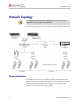
Configuration Guide Network Topology It is important to note that this configuration is not necessarily applicable to all customer environments. The following topology was tested during VIEW Certification testing. Known Limitations No limitations were discovered during VIEW Certification testing. VIEW Certification testing verifies that the wireless telephone and the AP interoperate at the packet level; therefore, no add-on vendor features were tested in the scope of VIEW. 4 PN: 1725-36080-001_J.
Aruba Mobility Controllers: A200, A800, A2400, A6000 Deployment Description It is a SpectraLink requirement that voice users be placed on a separate VLAN (e.g., VLAN 10) and data users on a separate VLAN (e.g., VLAN 25). The voice and data VLANs reside on the Aruba mobility controller and not on the access points (APs). The user traffic is tunneled back to the Aruba controller for processing. The edge network thus does not have to be modified to accommodate the WiFi clients and the VoWiFi network.
Configuration Guide Connecting to the Mobility Controller Command, comment, and screen text key In the sections below you will find commands, comments, prompts, system responses, or other screen-displayed information involved in the configuration process. This key explains the text styles and symbols used to denote them.
Aruba Mobility Controllers: A200, A800, A2400, A6000 Via the CLI By default, only SSH (Secure Shell) access to the switch (mobility controller) is permitted. 1. From a management system that has network connectivity to the switch, connect to the switch using SSH: ssh admin@ 2. Enter the admin password at the password prompt. 3. Type enable at the > prompt to enter the enable mode. 4. Type the enable password when prompted for a password.
Configuration Guide Initial Setup Before starting, please ensure that the Policy Enforcement Firewall module license is enabled on the Aruba mobility controller. Please contact Aruba Networks for licenses and installation information. On power-up, the user is presented with the startup wizard: Enter System name [Aruba800]: Aruba Enter VLAN 1 interface IP address [172.16.0.254]: Enter VLAN 1 interface subnet mask [255.255.255.
Aruba Mobility Controllers: A200, A800, A2400, A6000 . . . . . <<<<< Welcome to Aruba Wireless Networks - Aruba 800 >>>>> . . . . (Aruba) User: PN: 1725-36080-001_J.
Configuration Guide Assigning an IP to the Mobility Controller 1. Connect to the switch via the CLI. 2. Login with the configured username and password, admin/admin in this example. 3. Type enable at the > prompt. 4. Type the enable password, enable in this example. 5. Type configure terminal at the # prompt. 6. Create the VLAN for the voice (vlan 25) using the VLAN command: (Aruba) (config) #vlan 25 7. Create the VLAN interface. (Aruba) (config) #interface vlan 25 8.
Aruba Mobility Controllers: A200, A800, A2400, A6000 Connecting APs Provisioning APs The APs need to be provisioned. The Aruba APs can be provisioned manually or be configured for automatic provisioning. For manual provisioning, use the Web-based AP provisioning Web page. Refer to the AP Provisioning User Guide for instructions on provisioning the AP. The APs can communicate with the controller over a L2 or L3 network.
Configuration Guide SSID Configuration CLI command configuration APs can be configured using the CLI or the Web interface. Each AP is identified by a unique location code. The APs can either be configured per location with unique settings using the AP’s unique location code or globally using the wildcard location. “0” is used as the wildcard. Example: ap location 0.0.0 will configure all Aruba APs on the WLAN system. Both the Aruba APs and the Spectralink handsets support the 802.11a and the 802.
Aruba Mobility Controllers: A200, A800, A2400, A6000 Web-based configuration 1. Click the Configuration button. 2. In the navigation pane, select Network from the WLAN sub-menu. 3. To edit an existing AP profile, click the Edit button corresponding to the SSID. 4. To add a new profile, click the Add button. 5. Under Add SSID, enter aruba in the SSID field. 6. Select 802.11a/b/g from the Radio Type drop-down list to apply the SSID settings to the a/b/g radio. 7.
Configuration Guide Access Point Configuration Radio setting 802.11b or 802.11g When using the 802.11b/g band for the VoWiFi network, set the radio settings to 802.11b/g mixed mode. Preamble settings The tests on the Aruba system were run with the short preamble setting. The short preamble setting can be used, as this supports both short and long preambles. SpectraLink Wireless Telephones only support long preamble when using the 802.11b radio. When using a dual-radio AP, use the 802.
Aruba Mobility Controllers: A200, A800, A2400, A6000 For additional details on RF deployment please see the Deploying Enterprise-Grade Wi-Fi Telephony white paper and the Best Practices Guide for Deploying SpectraLink 8020/8030 Wireless Telephones. Recommended AP configuration settings CLI Commands Required Settings Default Settings 0 Max-clients 40 Beacon-interval Set to default 100 milliseconds The interval at which beacons are sent out .
Configuration Guide CLI Commands Required Settings 802.11b/g Tx rates (if all wireless client are 802.11g) These rates should be determined from RF site survey. Verify you have sufficient coverage to support data rates. 802.11a rates These rates should be determined from RF site survey. Verify you have sufficient coverage to support data rates. 6,9,12,24 802.11a Tx rates These rates should be determined from RF site survey. Verify you have sufficient coverage to support data rates.
Aruba Mobility Controllers: A200, A800, A2400, A6000 CLI command configuration All of the commands listed in the CLI Commands column above must be entered under the ap location command. The format is: ap location x.y.z phy-type g (To make the changes for the “g” radio.) commands ! phy-type a (To make the changes for the “a” radio.) commands ! Web-based configuration 1. Click the Configuration button. 2. In the navigation pane, select Radio from the WLAN sub-menu. 3. Click the 802.11b/g tab. 4.
Configuration Guide 18 PN: 1725-36080-001_J.
Aruba Mobility Controllers: A200, A800, A2400, A6000 10. Click the 802.11 a tab. 11. For Max Retries, enter 2 for voice. 12. For the DTIM period, enter 3. 13. For Basic Rates and Supported Rates, consult the facilities RF site survey to determine if coverage is sufficient to support all data rates. 14. To assign the power and channel setting manually: a. For ARM Assignment, select Disabled. b. Clear the ARM Scanning check box. c. Set the Default Channel and Initial Transmit Power from their dropdown lists.
Configuration Guide Dynamic RF Management — ARM Aware Scanning If Adaptive Radio Resource Management (ARM) Aware Scanning (RF scanning) is included in your firmware release, it can be enabled through the command line interface as follows: configure terminal ap location x.y.
Aruba Mobility Controllers: A200, A800, A2400, A6000 Security Policies and QoS Once the basic infrastructure is configured, it is necessary to configure the security policies to ensure that the data network and the voice network are secured and access to these networks is limited as required. The steps are as follows: 1. Setup aliases for the SVP Server. 2. Set policies for the wireless telephone user to the required voice server, DHCP and TFTP servers.
Configuration Guide Create policies for the wireless telephone user The policies shown in the above example can be configured using the Web interface as follows: 22 PN: 1725-36080-001_J.
Aruba Mobility Controllers: A200, A800, A2400, A6000 Assign policies to the role Create a role, for example phones, and assign the policies to this role. This is the role that would be assigned to the handsets when they are authenticated successfully. The Security Policies and QoS can also be configured through the command line interface (CLI). The CLI commands corresponding to this section are as follows: configure terminal netdestination tftp-server host 10.168.0.20 ! netdestination svp_server host 10.
Configuration Guide alias svp_server user svc-svp permit queue high user alias tftp-server svc-tftp permit user alias dhcp-server svc-dhcp permit user host 224.0.1.116 any permit ! user-role phones session-acl phone_acl ! 24 PN: 1725-36080-001_J.
Aruba Mobility Controllers: A200, A800, A2400, A6000 Authentication In addition to the encryption, Aruba recommends the use of MAC authentication to authenticate the Spectralink handsets. On the Aruba System, the roles for SpectraLink Wireless Telephones are derived using MAC-authentication. The wireless telephones can be authenticated individually using MAC-authentication or as a group using the vendor OUI and derivation rules. For instruction on enabling MAC-authentication refer to Aruba’s user guide.
Configuration Guide Quality of Service (QoS) Quality of service is achieved by prioritizing the SpectraLink voice traffic over data traffic. To prioritize the voice traffic over data traffic in the AP traffic queues, the “queue high” tag is used at the end of each ACL to prioritize the traffic matching the ACL over all other traffic.
Aruba Mobility Controllers: A200, A800, A2400, A6000 Subnet Roaming The Aruba system can be set up to support inter-switch inter-subnet roaming. The topology is as shown in the figure on page 2. When two or more switches are used in the Aruba WLAN system, one switch has to be identified as the master and the others as the local switch.
Configuration Guide CLI Commands to Set Up Subnet Roaming Commands for the master switch (the Aruba 800) Configure terminal ip default-gateway ap location 1.1.0 (#ap connected to 800) lms-ip ap location 1.2.0 (#ap connected to 6000) lms-ip ip route 224.0.0.0 255.0.0.0 exit write mem Commands for the local switch (the Aruba 6000) The AP’s IP address must be on the same subnet as the switch.
Aruba Mobility Controllers: A200, A800, A2400, A6000 It’s also necessary to set the default gateway of the SpectraLink 8000 SVP Server and SpectraLink 8000 Telephony Gateway to the IP address of the router connected to the master switch. CLI Commands to Verify Setup for Subnet Routing From the Aruba 800 show master ip show stm connectivity (should be 800’s ip) (shows the APs connected to the Aruba 800 switch) Ping the local switch. Pings should be successful.
Configuration Guide Checking the Configuration Verify connectivity by pinging between the switches, the APs, and the server and gateway. The switch and AP are now ready for use with the SpectraLink Wireless Telephones. To show AP settings: show ap config location x.y.z To show all APs connected to a switch: show stm connectivity To show clients associated to all APs: show station-table To show clients associated to a specific AP: show ap status 30 PN: 1725-36080-001_J.