Administrator’s Guide for the V500 System December 2004 Edition 3725-21743-003/B V500 Version 7.5 VideoVoiceDataWeb Connect. Any Way You Want.
Trademark Information Polycom® and the Polycom logo design are registered trademarks of Polycom, Inc. V500™, Global Management System™, People+Content IP™, Pro-Motion™, and Siren™ are trademarks of Polycom, Inc. in the United States and various other countries. All other trademarks are the property of their respective owners. Patent Information The accompanying product is protected by one or more U.S. and foreign patents and/or pending patent applications held by Polycom, Inc. © 2004 Polycom, Inc.
About this Guide The Administrator’s Guide for the V500™ System is for administrators of the V500 system who need to: ❑ Configure the system for use in the network environment ❑ Customize the behavior and appearance of the system ❑ Obtain information about calls ❑ Gather network usage and performance data ❑ Troubleshoot any issues Other documents available for the V500 system include: ❑ Setting Up the System, which describes how to set up the hardware ❑ Getting Started Guide for the V500 System, which des
Administrator’s Guide for the V500 System iv www.polycom.
Contents Chapter 1 - Introducing the V500 System Key Features .......................................................................................................................................... 1 - 2 Industry-Leading Audio and Video Quality ............................................................................. 1 - 2 Rich Conference Experience ......................................................................................................... 1 - 2 Enhanced User Experience ................
Administrator’s Guide for the V500 System Checking System Status ..................................................................................................................... 3 - 24 Keeping your Software Current ....................................................................................................... 3 - 25 Chapter 4 - Designing the User Experience Managing User Access to Settings and Features .............................................................................
Adding My Information ............................................................................................................... 5 - 7 Requesting Technical Support from the Global Management System Administrator ....... 5 - 8 Setting Up SNMP .................................................................................................................................. 5 - 9 Downloading MIBs ...............................................................................................................
Administrator’s Guide for the V500 System viii www.polycom.
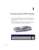
1 Introducing the V500 System Your V500 video conferencing system is a state-of-the-art visual collaboration tool. With crisp, clean video and crystal-clear sound, your V500 system provides the essential tools your home or small business needs for video conferencing over broadband networks. When you use a V500 system for meetings, you can exchange ideas and share documents with people anywhere in the world, as if they were all in the room with you.
Administrator’s Guide for the V500 System Key Features Industry-Leading Audio and Video Quality ❑ Best-in-class video algorithms — The H.264 video algorithm provides smooth, natural TV-like video. ❑ State-of-the-art audio quality — The V500 system offers Polycom Siren™ 14, a 14 kHz frequency response that delivers CD-quality sound. ❑ Video error concealment — The H.
Chapter 1 - Introducing the V500 System ❑ Many ways to use the directory — Find information in the directory using the method you find most convenient. ❑ Call Scheduler — Use the calendar and call scheduling feature to schedule video conferences. The system automatically calls the site you selected on the date and time you specified. For recurring calls, you can indicate whether you want the system to automatically make the call daily, weekly, or monthly.
Administrator’s Guide for the V500 System ❑ Room monitoring — Monitor rooms in or out of a call using the Web Director feature, accessible through the V500 web interface. ❑ Call Detail Reports — Access the system’s call history from the V500 web interface. You can download the data to a spreadsheet application for sorting and formatting. ❑ Remote diagnostics — Identify and correct issues that affect the video conferencing experience using tools in the V500 web interface.
Chapter 1 - Introducing the V500 System Name Component Description Power supply The power supply connects power to the system. Documentation Read Me First Setting Up the V500 System V500 system documentation CD Optional System Components To extend what you do with your V500 system, the following additional options are available. ❑ Single BRI network interface — Connect to ISDN with your V500 system. ❑ Headphone — Listen privately by adding your own headphone using the 3.5 mm stereo mini jack.
Administrator’s Guide for the V500 System 1-6 www.polycom.
2 Setting Up Your System Hardware This chapter describes detailed system setup information. You can also refer to the system setup document that was provided with your system. For optional components, refer to the setup sheet that was shipped with the component. © Polycom, Inc.
Administrator’s Guide for the V500 System Positioning the System The V500 system is designed for homes, home offices, and small- to medium-sized businesses. To position the system: >> Place the V500 system on top of your TV monitor. For optimal audio and video performance, locate the monitor within 5 to 10 feet (1.52 to 3.05 meters) away from the people in the call. 5'-10' 1. Connecting the Monitor You must connect a television monitor to the V500 system.
Chapter 2 - Setting Up Your System Hardware S-video provides superior video quality, and is recommended. 2. Connect the system’s audio outputs to the monitor’s audio inputs using the red and white connectors on the monitor cable. After you have finished setting up the system, you will need to configure the monitor’s behavior. You can find information on how to do this in Configuring the TV Monitor on page 4-7.
Administrator’s Guide for the V500 System Connecting the BRI Network Interface The V500 system is available with the optional BRI network interface, which allows you to make ISDN calls. You may need an NT-1 device if your site does not use an internal telephone system (PBX). A PBX or an NT-1 device provides the S/T interface that the system’s BRI network interface requires. To install the BRI network interface: 1. Make sure the system is powered off. 2.
Chapter 2 - Setting Up Your System Hardware Installing Batteries in the Remote Control The remote control uses three AAA batteries, which are included with the system. To install batteries in the remote control: 1. Remove the battery cover from the back of the remote control. 2. Refer to the diagram inside the remote control, and install the batteries in the orientation shown. 3. Reinstall the battery cover on the remote control. Connecting Power The V500 system has an external power supply.
Administrator’s Guide for the V500 System 2-6 www.polycom.
3 Configuring Network Use The V500 system is factory configured to enable you to easily and quickly make video calls in most network situations. In many cases, you simply need to physically connect the system as described in Chapter 2, power it on, and follow the setup wizard. However, because networks vary from business to business and home to home, you may need to change some of the default settings or perform other network configuration.
Administrator’s Guide for the V500 System Using the Setup Wizard When you power on the system for the first time, a setup wizard begins to run. The setup wizard automatically detects your system’s IP and ISDN connections, and it leads you through the minimum steps you need to take to place a video call. As you go through the setup wizard, you may need additional information or you may want to change a default setting. If this is your situation, refer to the rest of this chapter.
Chapter 3 - Configuring Network Use Configuring Your IP Connection To configure your IP network connection, you need to: ❑ Configure LAN properties ❑ Set up your IP network connection ❑ Configure IP network support Configuring LAN Properties The first step in setting up your IP connection is to configure the LAN properties.
Administrator’s Guide for the V500 System 2. Configure these settings: Setting Description Connect to my LAN Check this to specify whether the system is part of the LAN. Allow IP Calls Check this to enable the system to make and receive IP calls. Host Name Indicates the system’s DNS name. If you change the Host Name, the system restarts.
Chapter 3 - Configuring Network Use Setting Description LAN Speed Specify the LAN speed to use. Note that the speed you choose must be supported by the switch. Choose Auto to have the switch negotiate the speed automatically. If you choose 10 Mbps or 100 Mbps, you must also select a duplex mode. Note: The LAN speed setting for the V500 and the switch must match. Polycom strongly recommends that you do not select Auto for either only the V500 or only the router; the settings for both must be the same.
Administrator’s Guide for the V500 System If, therefore, you’re limiting your calls to other systems within your intranet, you don’t need to perform any additional network configuration to use your V500. Simply go on to the next section, Configuring IP Network Support on page 3-13. Calling Through a Cable or DSL Modem You can access the network and make video calls by directly connecting your V500 to a cable modem or Digital Subscriber Line (DSL) modem, without using a network router.
Chapter 3 - Configuring Network Use ❑ A firewall acts as a security barrier between one network and another. Often that barrier is between a smaller network, like you might have at your home or business, and an exterior network, such as the Internet. The firewall prevents unsolicited external network traffic from accessing your internal network. Because NATs and firewalls provide security for your network, they limit outside access to your internal network.
Administrator’s Guide for the V500 System Refer to the Port Usage section in Appendix if you want advanced port configuration information. NetGear Routers The following procedure applies to NetGear MR814v2 and RP614v2 routers. If you have a different NetGear model, the settings may vary slightly. This procedure assumes that your router is correctly configured and connected to the Internet and that your network is operational. To configure a NetGear router: 1.
Chapter 3 - Configuring Network Use Linksys Routers The following procedure applies to the Linksys BEFSX41 router. If you have a different Linksys model, the settings may vary slightly. This procedure assumes that your router is correctly configured and connected to the Internet and that your network is operational. To configure a Linksys router: 1. In a browser such as Internet Explorer, type the IP address of your router, which you can find in your router’s documentation. 2.
Administrator’s Guide for the V500 System D-Link Routers The following procedure applies to the D-Link DI-604 router. If you have a different D-Link model, the settings may vary slightly. This procedure assumes that your router is correctly configured and connected to the Internet and that your network is operational. To configure a D-Link router: 1. In a browser such as Internet Explorer, type the IP address of your router, which you can find in your router’s documentation. 2.
Chapter 3 - Configuring Network Use Configuring Firewall and NAT Properties Once you’ve set up your router, you must configure the V500 system so that it works with the firewall and NAT. Before making changes on the Firewall screen, you should know whether or not your firewall device is H.323 compatible. Firewall devices that are H.323 compatible have been programmed with logic that can detect H.323 video conferencing traffic as it passes between the LAN and WAN.
Administrator’s Guide for the V500 System Setting Description NAT Configuration Specify whether the system should attempt to determine the NAT Public WAN Address automatically. • If the system is behind a NAT that allows HTTP traffic, select Auto. The system will attempt to automatically discover the NAT Public WAN Address. • If the system is behind a NAT that does not allow HTTP traffic or if Auto fails to discover the NAT Public WAN address, select Manual.
Chapter 3 - Configuring Network Use There are two types of DMZs: ❑ Virtual DMZ — With a virtual DMZ, all ports through the router are opened for the device in the DMZ (in this case, the V500). This has the affect of placing the V500 on the outside of the router’s firewall. Keep in mind, however, that the V500 may still be protected by some global firewall securities, which may adversely affect video conferencing.
Administrator’s Guide for the V500 System To configure H.323 settings: 1. Go to System > Admin Settings > Network > IP > H.323 Settings. 2. Configure these settings: Setting Description Enable IP H.323 Check this to allow IP dialing. Display H.323 Extension Check this if you want to place gateway calls by entering the H.323 extension separately from the gateway ID.
Chapter 3 - Configuring Network Use Setting Description Outbound Call Route If your system uses a gatekeeper, you can specify whether outbound ISDN calls are routed through an IP-to-ISDN gateway or through an ISDN line directly connected to the V500 system. Gatekeeper IP Address If you chose to use an automatically selected gatekeeper, this field automatically displays the gatekeeper’s IP address. If you chose to specify a gatekeeper, enter the IP address of the gatekeeper here.
Administrator’s Guide for the V500 System Be sure to configure the gateway to use the same prefixes and suffixes you define for the system. Configuring SIP Settings The Session Initiation Protocol (SIP) is a signaling protocol for Internet conferencing. If you are unfamiliar with SIP, Polycom recommends that you do not change the default settings. To configure the SIP settings if your network supports SIP: 1. Go to System > Admin Settings > Network > IP > SIP Settings. 2.
Chapter 3 - Configuring Network Use Configuring Quality of Service (QOS) If your network is configured to recognize and prioritize network traffic using QOS, you can configure the V500 system to mark IP packets with the values recognized by your network. Keep in mind that enabling QOS on the V500 is not enough; all devices in the network path must also be configured for QOS. If you are unfamiliar with QOS, Polycom recommends that you do not change the default settings.
Administrator’s Guide for the V500 System Configuring Your ISDN Connection If you have the ISDN option, you can connect your V500 through ISDN as well as through one of the IP network connections described earlier in this chapter. Preparing Your ISDN Network Before you set up your connection using ISDN: 1. Refer to the Preparing Your Network for Collaboration document, available at www.polycom.com/videodocumentation.
Chapter 3 - Configuring Network Use Setting Description ISDN Voice Algorithm Enter which voice algorithm (Alaw or uLaw) you want to use for ISDN voice calls. Do not change this setting unless you experience audio issues in all ISDN voice calls. Auto BRI Configuration Check this to allow the NI-1 switch to automatically configure the directory numbers and SPIDs. This setting is only available if you have selected the NI-1 switch protocol. 3.
Administrator’s Guide for the V500 System Configuring Call Preferences Call preferences help you manage the network bandwidth used for calls. For example, you can specify the default and optional call settings for outgoing calls, and limit the call speeds for incoming calls. If you have just set up your network, use the screens described in this section to specify your call settings.
Chapter 3 - Configuring Network Use 4.
Administrator’s Guide for the V500 System Configuring the Global Directory If you use the Polycom Global Management System, you can configure your system to use the Global Directory. The Global Directory provides a list of other systems that are registered with the Global Directory Server and are available for calls. The other systems appear in the Directory, allowing you to place calls to other users by selecting their names.
Chapter 3 - Configuring Network Use Setting the Dialing Rules If your system is connected to a private network and also to a public network, you may need to specify the codes and prefixes necessary for dialing other systems. To set the dialing rules: 1. Go to System > Admin Settings > Global Services > Dialing Rules. 2. Configure these settings: Setting Description Always Dial Area Code Specifies that calls to sites in the same area code must include the area code.
Administrator’s Guide for the V500 System If you have trouble making video calls: ❑ Make sure the number you dialed is correct, then try the call again. For example, you may need to dial 9 for an outside line or include a long distance access code or country code. ❑ To find out if the problem exists in your system, ask the person you were trying to reach to call you instead. ❑ Find out if the system you are calling has its power turned on and is functioning properly.
Chapter 3 - Configuring Network Use Keeping your Software Current If you have Internet access and a software key, you can use the web-based Softupdate application to upgrade the V500 software. If you do not have Internet access, your reseller can supply you with the V500 software update on CD-ROM. To upgrade your software via the Internet: 1. Before you begin, read the Release Notes, available at the Polycom Resource Center at www.polycom.com, for information about the latest software version. 2.
Administrator’s Guide for the V500 System 3 - 26 www.polycom.
4 Designing the User Experience Everybody who uses the Polycom V500 system has different needs. That’s why your system has a customizable user interface. You can design the video conferencing experience to meet your needs and the needs of any other users who use the system. You can customize the behavior of the system, and then build in various access levels for the different users, depending on how much or how little you want them to change system behaviors.
Administrator’s Guide for the V500 System Managing User Access to Settings and Features You can manage access to various settings and features by using passwords and by configuring the system to show only those options you want other users to see. To maintain this security level: You can allow users to: High Call only the numbers you specify on the home screen. (Kiosk mode) See Using the System for Specialized Applications on page 4-5 and Designing the Home Screen on page 4-18.
Chapter 4 - Designing the User Experience To reset a forgotten Admin Password: 1. Get the system’s serial number from the system or from the System Information screen. 2. Go to System >Diagnostics > Reset System. 3. Enter the system’s serial number and select Delete System Settings. 4. Select Reset System. When the system completes the reset, it leads you through the setup wizard. You can enter a new Admin Password when you set up the system.
Administrator’s Guide for the V500 System Letting Users Customize the Workspace You can allow other users of the V500 system to change common user preferences by providing access to the User Settings screen. To allow users to customize the workspace: 1. Go to System > Admin Settings > General Settings > Security. 2. Check the Allow Access to User Settings option to make the User Settings button available to users on the System screen.
Chapter 4 - Designing the User Experience Limiting What Users Can Do With the System You can limit what you allow other users to do with the system by configuring the following: ❑ Maximum Time in Call — If you want to specify the maximum time a call can last, go to System > Admin Settings > General Settings > System Settings > Call Settings and enter the maximum call length allowed.
Administrator’s Guide for the V500 System Configuring Camera Settings The Camera screen lets you specify camera settings. To configure camera settings: 4-6 1. Go to System > Admin Settings > Camera. 2. Configure these settings: Setting Description Backlight Compensation Specifies whether to have the camera automatically adjust for a light background. Backlight compensation is best used in situations where the subject appears darker than the background.
Chapter 4 - Designing the User Experience Configuring the TV Monitor The V500 system allows you to customize the display to suit your room and equipment configuration. To configure the TV monitor: 1. Go to System > Admin Settings > Monitor. 2. Configure these settings: Setting Description Monitor Specifies the monitor’s aspect ratio: • 4:3 — Select if you are using a regular TV monitor. • 16:9 — Select if you are using a wide screen monitor and configuring for dual-monitor emulation.
Administrator’s Guide for the V500 System Using Dual Monitor Emulation With Dual Monitor Emulation, you see both near and far sites on one TV monitor in two different views. During presentations, you see content and the near and far sites. Setting Up On the monitor’s setup menu, select the full-screen setting that stretches the picture uniformly, without clipping. On the TV Monitor screen: 1. If you are using a wide screen monitor, set Monitor to 16:9. Otherwise, set Monitor to 4:3. 2.
Chapter 4 - Designing the User Experience Adjusting the Monitor’s Color Balance In most cases, the monitor you connect to your system provides natural color without any adjustment. Depending on your environment as well as the model of monitor, however, the video may exhibit one of these problems: ❑ Picture is too dark ❑ Colors appear faded ❑ Picture has too much of one color — for example, the picture may appear greenish If you notice any of these, the monitor needs to be adjusted.
Administrator’s Guide for the V500 System ❑ Install People+Content IP on the computer(s) that the presenter will use to show content.
Chapter 4 - Designing the User Experience 4. When prompted, download the file locally. 5. Follow the steps in the Setup Wizard to finish installing the application on the computer. Anyone using that computer can then double-click on the People+Content IP icon to present content during video conferences using the V500 system. Make the application available to all users in your organization by downloading the setup.exe file to a local location that everyone can access.
Administrator’s Guide for the V500 System Designing General System Behaviors You can configure the following general system behaviors to accommodate the needs of your organization: ❑ Call Settings ❑ Remote Control Behavior ❑ Directory Settings ❑ Call Answering Mode ❑ AES Encryption ❑ Passwords and Security Options ❑ Date, Time, and System Location Configuring Call Settings The Call Settings screens provide access to high-level options for the entire system.
Chapter 4 - Designing the User Experience Setting Description Recent Calls Specifies whether to display the Recent Calls button on the home screen. The Recent Calls screen lists the site number or name, the date and time, and whether the call was incoming or outgoing. Note: If the Call Detail Report option is not selected, the Recent Calls option is not available. Far Site Name Display Time Specifies the time period the far-site name appears on screen when calls first connect.
Administrator’s Guide for the V500 System Setting Description Confirm Directory Additions Specifies whether you are prompted to confirm new directory entries when saving the information for the last site called. Confirm Directory Deletions Specifies whether you are prompted to confirm deletions of directory entries. Setting the Call Answering Mode You can choose to answer calls automatically or manually, or you can set the system to automatically refuse any incoming calls.
Chapter 4 - Designing the User Experience Setting Passwords and Security Options You can enter or change the administrator and meeting passwords as well as specify whether to allow remote access to the system. To set passwords and security options: 1. Go to System > Admin Settings > General Settings > Security. 2. Configure these settings: Setting Description Admin Password Enter or change the Admin password.
Administrator’s Guide for the V500 System Setting Date, Time, and Location You can update the system with regional settings, including the location-specific language and calling parameters. To set the date, time, and location: 1. Go to System > Admin Settings > General Settings > Location. 2. Configure these settings: Setting Description Country Specifies the country where the system is located. Changing the country automatically adjusts the country code associated with your system number.
Chapter 4 - Designing the User Experience Customizing the Workspace Appearance You can customize the V500 system workspace appearance to suit your environment functionally and aesthetically. For example, by customizing the home screen into kiosk mode, anyone who uses the system only has to select a site and press the Call button on the remote control to place a call.
Administrator’s Guide for the V500 System Designing the Home Screen Customize the system functionality according to your needs, skill level, and environment. Use the marquee to add instructions Infrequent Users (Kiosk Mode) Provide a simple workspace so no training is needed: • Let users make calls to pre-defined numbers with one button click. • Include instructions on screen.
Chapter 4 - Designing the User Experience To design the home screen: 1. Go to System > Admin Settings > General Settings > Home Screen Settings. 2. Configure these settings: Setting Description Dialing Display Specifies which dialing option to display: • Dialing entry field — Allows users to enter numbers manually. • Display marquee — Displays text in the dialing entry field. Can be used to display user instructions. Users cannot enter numbers manually when this option is selected.
Administrator’s Guide for the V500 System 4. Select and configure these settings: Setting Description Sites Allows users to access any pre-defined sites from a My Contacts/Speed Dial list on the home screen. Last Number Dialed Specifies whether to display the last number dialed or clear the address box on the home screen. Adding Sites to the Home Screen Creating Site buttons on the home screen makes it easy for you to place calls to sites that you call on a regular basis.
Chapter 4 - Designing the User Experience To enter marquee text: 1. Go to System > Admin Settings > General Settings > Home Screen Settings. 2. In Dialing Display, select Display Marquee and enter the text. You can also add marquee text through the V500 web interface. Using Screen Saver Text You can customize the V500 system to display text when the system is in sleep mode. For instance, you can display on-screen instructions. To enter screen saver text: 1. On a PC, open a web browser. 2.
Administrator’s Guide for the V500 System 2. Configure these settings: Setting Description Color Scheme Customizes the look of your system with different color schemes. Screen Saver Wait Time Specifies how long the system remains awake during periods of inactivity. The default is 3 minutes. You can allow users to change color schemes by allowing user access to the User Settings screen. Setting Ring Tones and Alert Tones To set ring tones and alert tones: 1. Go to System > Admin Settings > Audio.
Chapter 4 - Designing the User Experience Audio Options for Closed Captioners When you provide captions for a conference, the captioner may be present, or may use a telephone or web browser to listen to the conference audio.
Administrator’s Guide for the V500 System 5. In the Closed Caption screen, type the caption text into the text field. Text wraps to the next line after 59 characters. 6. Press Enter to send the text to the sites in the conference. Providing Captions Via a Telnet Session Closed captioners can provide captions from inside the conference room, or from a remote location, by entering captions via a Telnet session, as shown in the diagram below.
Chapter 4 - Designing the User Experience Getting Started with Calling The system is installed and you’ve finished the network configuration and designed the behaviors. Now it’s time for you to start placing calls. You may want to spend time becoming familiar with basic calling tasks. The following resources are available: ❑ V500 System Getting Started Guide — This guide is for all users, from beginners to the more experienced.
Administrator’s Guide for the V500 System 4 - 26 www.polycom.
5 Managing the System Remotely You configure, manage, and monitor the system from a remote computer using the V500 web interface (the system’s web interface), the Polycom Global Management System, or SNMP. Your choice of management tool depends on your network environment: ❑ V500 web interface requires only a web browser to control the system. ❑ Polycom Global Management System requires the Global Management System application to be installed on your network.
Administrator’s Guide for the V500 System Using the V500 Web Interface You can use the V500 web interface to perform most of the calling and configuration tasks you can perform on the local system. Accessing the V500 Web Interface To configure your browser to use the V500 web interface: 1. Be sure that you use Microsoft Internet Explorer 6.0 or later as your web browser. 2.
Chapter 5 - Managing the System Remotely Room Monitoring with the V500 Web Interface The Web Director feature within the V500 web interface allows administrators of the V500 system to monitor a call or the room where the system is installed. For security reasons, this feature can only be enabled on the local system by an administrator. To enable room monitoring: 1. Go to System > Admin Settings > General Settings > Security. 2. Select Allow Video Display on Web to allow the room to be viewed remotely.
Administrator’s Guide for the V500 System Managing System Profiles with the V500 Web Interface The customization options for V500 systems have been extended with the ability to store your system settings as separate profiles. Profiles can be stored on your PC as a .csv file using the V500 web interface. There is no limit to the number of profiles you can save. This is particularly useful if you are managing systems that support multiple applications.
Chapter 5 - Managing the System Remotely Managing Directories with the V500 Web Interface The V500 web interface import/export directory feature allows you to efficiently maintain consistency of V500 system directories. It is particularly useful if you are managing multiple systems that call the same locations.
Administrator’s Guide for the V500 System Configuring Global Services If you use the Polycom Global Management System, you can configure, manage, and monitor the V500 system using the Global Management System server. The Global Management System is a web-based client/server software tool that allows administrators to manage a network of video conferencing systems.
Chapter 5 - Managing the System Remotely To require an account number for calls: 1. Go to System > Admin Settings > Global Services > Account Validation. 2. Specify whether to require an account number for placing calls and whether that number should be validated by the Global Management System server. Adding My Information If your system is managed by the Global Management System, you can configure the V500 system so that you can request help from the Global Management System administrator.
Administrator’s Guide for the V500 System Requesting Technical Support from the Global Management System Administrator 1. From the Place A Call screen, press 2. Select Support and press on the remote. on the remote. You see the following message: Tech Support will be alerted to phone you at the following number. Continue? Enter your contact telephone number. The V500 system sends your information to the Global Management System administrator.
Chapter 5 - Managing the System Remotely Setting Up SNMP The V500 system sends SNMP (Simple Network Management Protocol) reports to indicate a total of 31 conditions, including the following: • All alert conditions found on the V500 system’s alert page • Details of jitter, latency, and packet loss • Low battery power is detected in the remote control • A system powers on after a long period powered off • Administrator logon is successful or unsuccessful • A call fails for a reason other than a b
Administrator’s Guide for the V500 System Configuring for SNMP Management To configure the V500 system for SNMP management: 1. 2. 5 - 10 Access the SNMP configuration screen either in the V500 web interface or on the V500 system: • In the V500 web interface, go to System Setup > Admin Settings > Global Services > SNMP. • On the V500 system, go to System > Admin Settings > Global Services > SNMP.
6 System Usage and Statistics The V500 system provides various screens that allow you to review information about calls made by the system and to review network usage and performance. © Polycom, Inc.
Administrator’s Guide for the V500 System Call Summary The Call Summary screen provides details about the calls placed by the system, including: ❑ Duration of the last call ❑ Total number of calls placed and received ❑ Number, total time, and percentage of IP calls ❑ Number, total time, and percentage of ISDN calls To view the Call Summary screen: 6-2 >> Go to System > Diagnostics > Call Statistics and then select three times.
Chapter 6 - System Usage and Statistics Call Statistics The two Call Statistics screens provide information about the call in progress, including: This screen: Displays this information: Call Statistics (1) • Call speed (transmit and receive) • Video protocol, annexes, and format in use (transmit and receive). The video protocol is shown in green if the system is currently using error concealment.
Administrator’s Guide for the V500 System Call Status The Call Status screen provides call connection information. The spheres on the screen provide details for each line. When you place a call, you’ll see the status change as the call connects. To view the Call Status screen: >> Go to System > Diagnostics > Call Statistics. You can highlight the spheres on this screen to see the number dialed, the relevant status code, and details of any errors.
Chapter 6 - System Usage and Statistics Recent Calls Recent Calls shows a list of up to 99 calls made by the system. It includes the following information: ❑ Site name or number ❑ Date ❑ Time ❑ Call In or Out The Recent Calls list shows incoming and outgoing calls that connect, as well as outgoing calls that do not connect. If Do Not Disturb has been enabled, any incoming calls attempted by other sites will not be listed. The Home screen can be configured to include Recent Calls.
Administrator’s Guide for the V500 System Call Detail Report The Call Detail Report (CDR) provides the system’s call history. You can view the CDR from the V500 web interface, and you can download the data in CSV format for sorting and formatting. CSV stands for Comma Separated Value. CSV files can be imported into spreadsheet and database programs. Every call that connects is added to the CDR, whether it is a call that you make or that you receive.
Chapter 6 - System Usage and Statistics Data Description Call Duration The length of the call. Account Number If Require Account Number to Dial is enabled on the system, the value entered by the user is displayed in this field. Remote System Name The far site’s system name. Call Field Number 1 The number dialed from the first call field, not necessarily the transport address. For incoming calls — The caller ID information from the first number received from a far site.
Administrator’s Guide for the V500 System 6-8 Data Description Video Format (Rx) The video format received from the far site, such as CIF or SIF. Disconnect Reason The description of the Q.850 (ISDN) cause code showing how the call ended. Q.850 Cause Code The Q.850 cause code showing how the call ended. Total H.320 Errors The number of errors during an H.320 call.
Chapter 6 - System Usage and Statistics Call Detail Report Archives Calls are added to the CDR until the file size reaches 50 KB, which is equivalent to about 150 calls. The system then automatically archives the CDR and creates a new CDR file. If an archive is already present, the new archive overwrites it. Each CDR starts with Row 1, but the conference numbers continue from the file most recently archived. Conference numbering restarts at 1 after the system assigns conference number 100,000.
Administrator’s Guide for the V500 System 6 - 10 www.polycom.
7 Diagnostics and General Troubleshooting This chapter covers the diagnostic screens of the V500 system. It is organized by category to help you troubleshoot any issue. Diagnostic tools are available via the system itself and the V500 web interface. To connect to the V500 web interface, enter your system’s IP address in a web browser and browse to the required diagnostic tool. © Polycom, Inc.
Administrator’s Guide for the V500 System Sending a Message If you are experiencing difficulties with connectivity or audio, you may want to send a message to the V500 system. Only the near site can see the message; it is not broadcast to the far site in the call. To send a message via the V500 web interface: 1. On a PC, open a web browser. 2. In the browser address line, enter the system’s IP address (for example, http://255.255.255.255) to go to the V500 web interface. 3.
Chapter 7 - Diagnostics and General Troubleshooting Diagnostic Screens You can view network statistics and perform diagnostic tests from the V500 system’s Diagnostics screens. To access the Diagnostics screens on the system: >> Go to System > Diagnostics. To access the Diagnostics screens from the V500 web interface: 1. On a PC, open a web browser. 2. In the browser address line, enter the system’s IP address (for example, http://255.255.255.255) to go to the V500 web interface. 3.
Administrator’s Guide for the V500 System Call Status Tools Diagnostic Tool In the system’s user interface In the V500 web interface Call Status screen On the Diagnostics screen, select Call Statistics. 1. Select Diagnostics > Call Statistics. Displays call type, data speed, and number dialed for the current call. In ISDN calls, this screen also displays connection status for each channel. Selecting a channel call progress indicator displays its ISDN number.
Chapter 7 - Diagnostics and General Troubleshooting Network Tools Diagnostic Tool In the system’s user interface In the V500 web interface Near End Loop test 1. On the Diagnostics screen, select Network. 1. Select Diagnostics > Network > Near End Loop. Tests whether your system is able to make IP calls successfully. Monitor 1 displays the video and plays the audio that would be sent to the far site in a call. 2. Select Near End Loop to start 2. Click the Near End Loop icon. the test. 3.
Administrator’s Guide for the V500 System Video and Audio Tools Diagnostic Tool In the system’s user interface In the V500 web interface Color Bar test 1. On the Diagnostics screen, select Video. 2. Click the Color Bars icon. Tests the color settings of your monitor for optimum picture quality. 2. Select the Color Bars icon. 1. Select Diagnostics > Video. 3. Click the Color Bars icon again to stop the test.
Chapter 7 - Diagnostics and General Troubleshooting Reset Diagnostic Tool In the system’s user interface In the V500 web interface Reset System 1. On the Diagnostics screen, select Reset System. 1. Select Diagnostics > Reset System. 2. Enter the system’s serial number. 2. Click the Reset System icon. Cycles power to the system.
Administrator’s Guide for the V500 System General Troubleshooting This section presents problems, likely causes, and corrective actions. Problems are grouped as follows: ❑ Power and Start-up ❑ Remote Control ❑ Access to Screens and System ❑ Calling ❑ Display ❑ Audio ❑ Error Indications ❑ System Lights ❑ Network Interface Lights Power and Start-up Symptom Problem Corrective action The system does not start or respond in any way The power switch is off.
Chapter 7 - Diagnostics and General Troubleshooting Remote Control Symptom Problem Corrective action The system does not respond to the remote control No batteries in the remote control. Install batteries in the remote control. The batteries are installed incorrectly in the remote control. Insert the batteries in the correct +/- position. The room lights operate in the 38 Khz range and interfere with the remote control signals. Turn off the lights in the room and try the remote control again.
Administrator’s Guide for the V500 System Symptom Problem Corrective action Cannot access the system remotely The system does not allow remote access. On the system, go to Admin Settings > General Settings > Security and enable web access. The system or your computer is not connected to the LAN. Check the LAN cable to the LAN port on the rear of the system. The LAN cable to the system or to your computer is bad. Replace the appropriate LAN cable. Check the LAN cable to your computer.
Chapter 7 - Diagnostics and General Troubleshooting Calling Symptom Problem Corrective action Error message occurs when placing an IP (H.323) call. The system is not connected to the LAN. Verify that the LAN cable is connected properly. The system’s LAN cable is bad. Replace the system’s LAN cable. The far site is not connected. Use the PING test (System > Diagnostics > Network > PING) to determine whether the far site is accessible to your system.
Administrator’s Guide for the V500 System Symptom Problem Corrective action Error message occurs when placing an ISDN (H.230) call. An ISDN cause code is received from the ISDN line. Try the call again. The highest-numbered channel did not connect. The system cannot make a call if this channel does not connect. Be sure you are calling the correct number. The number may need to include: For more information, please refer to Q.850 Cause Codes on page Appendix-4.
Chapter 7 - Diagnostics and General Troubleshooting Symptom Problem Corrective action Voice-only calls cannot be placed using the VSX system. This is normal. Place voice-only calls using the VTX 1000 conference phone. Hanging up the VTX 1000 conference phone does not end the video call. This is normal. Use the VTX 1000 conference phone’s EndVideo soft key or the VSX system remote control to end video calls.
Administrator’s Guide for the V500 System Symptom Problem Corrective action Picture is slow or jerky. The system is receiving video that includes a large amount of motion. A background with less motion provides a better, smoother video picture. Too many network line transmission errors. Check the error count on the Diagnostics > Call Statistics screen to verify this. Try the call again. Only one 64 Kbps channel is connecting in your call. Check the ISDN number of the far site.
Chapter 7 - Diagnostics and General Troubleshooting Audio Symptom Problem Corrective action No audio at your site The far site is muted. Look for the far site Mute icon. Ask the far site to unmute the microphone. Note: The far site’s microphone may be muted even if you do not see a far site Mute icon. The volume may be turned all the way down. Use the remote control to turn up the volume. The far site’s microphones are not placed correctly.
Administrator’s Guide for the V500 System Symptom Problem Corrective action The people at the far site cannot hear you. The people at your site are too far from the microphone. Move closer to the microphone. Your system’s microphone is muted. Check your system for one or more of these mute indications: • Near site mute icon on the screen • System indicator is red To unmute the system, press the Mute button on the remote control. Your system’s microphone does not work.
Chapter 7 - Diagnostics and General Troubleshooting Error Indications Symptom Problem Corrective action The System Information screen shows “waiting” in the IP Video Number field. The LAN is not working. Check the LAN connection. The DHCP server is not available. Contact your network service provider to correct the problem with the server or to assign a static IP address. The system displays a message stating that there are too many Global Directory entries.
Administrator’s Guide for the V500 System System Lights The system lights are located on the front of your V500 system. When the V500 system... It means... Indicators are off No power to the system. Green indicator blinks slowly The system is sleeping. Green indicator flashes when you use the remote control The system is not in a call, and is receiving signals from the remote control.
Chapter 7 - Diagnostics and General Troubleshooting How to Contact Technical Support If you are not able to make test calls successfully and you have verified that the equipment is installed and set up correctly, contact Polycom Technical Support by telephone or Internet as described below. By Telephone Before calling Polycom Technical Support, please have the following information ready.
Administrator’s Guide for the V500 System 7 - 20 www.polycom.
Appendix This appendix provides the following technical details about the V500 system: ❑ Cable Descriptions and Drawings ❑ Port Usage ❑ Q.850 Cause Codes Cable Descriptions and Drawings The following table gives information about the cables shipped with the system. Cable Maximum Approved Length Part Number Shipped LAN cable 100 ft (30 m) 2457-08343-001 Orange RJ-45 Composite video cable Triple RCA with S-video 12 ft (3.6 m) 2457-08674-001 6 ft (1.
Administrator’s Guide for the V500 System LAN Cable 3 WIRING COLOR CODE STANDARDS: (WIRE/STRIPE) P1 P2 PIN # PIN # 3.35" 1 CONN. RJ-45 ( x2 ) PIN 8 AT&T 258A/268B 1 1 WHITE/ORANGE 2 2 ORANGE/WHITE 3 3 WHITE/GREEN 4 4 BLUE/WHITE 5 5 6 6 GREEN/WHITE 7 7 WHITE/BROWN 8 8 BROWN/WHITE MOLDED STRAIN RELIE BOTH ENDS. PIN 8 P1 P2 CABLE, 8 COND, 24 AWG, BLACK PVC JACKET CATEGORY 5, TWISTED PAIR MINIMUN OF 2 TWISTS PER INCH.
Appendix Port Usage The following table lists the H.323 port usage for the V500 system. Use this information if you need to fully define the port rules for your network equipment. © Polycom, Inc. Port Function TCP or UDP 21 (FTP) Software upgrades and provisioning for V500 system TCP 23 (Telnet) For diagnostics 24 (Telnet) Trace log TCP 80-Static HTTP interface/ web management (optional) TCP 389-Static ILS registration (LDAP) TCP 1503-Static T.
Administrator’s Guide for the V500 System Q.850 Cause Codes The following table describes codes that the ISDN switch sends to the V500 system to indicate call status. Although the codes are standardized, each ISDN service provider defines them differently. Because of this, the definitions in the table may not exactly match the messages that you see.
Appendix © Polycom, Inc. Code Cause Definition 28 Invalid number format Destination address was incomplete or presented in an unrecognizable format, which prevented the connection from being established. 29 Facility rejected The network cannot provide the facility requested by the user. 30 Response to STATUS INQUIRY The equipment returns this message when it receives a STATUS INQUIRY message. 31 Normal, unspecified A normal event has occurred with no standard cause applying.
Administrator’s Guide for the V500 System Appendix - 6 Code Cause Definition 65 Bearer capability not implemented The network is not capable of providing the bearer capability requested by the user. 66 Channel type not implemented The requested channel type is not supported by the equipment sending this code. 69 Requested facility not implemented The remote equipment is not capable of providing the requested supplementary service.
Appendix © Polycom, Inc. Code Cause Definition 97 Message type nonexistent or not implemented The equipment received a message of a type that is invalid or not supported. This code indicates either a problem with the remote configuration or a problem with the local D channel. 98 Message incompatible with call state or message type nonexistent The equipment received a message that is not valid in the current call state. Cause 98 is usually due to a D-channel error.
Administrator’s Guide for the V500 System Appendix - 8 www.polycom.
Safety and Legal Notices Important Safeguards Read and understand the following instructions before using the system: • Close supervision is necessary when the system is used by or near children. Do not leave unattended while in use. • Only use electrical extension cords with a current rating at least equal to that of the system. • Always disconnect the system from power before cleaning and servicing and when not in use. • Do not spray liquids directly onto the system when cleaning.
Administrator’s Guide for the V500 System Limitation of Remedies and Damages Polycom, Inc., its agents, employees, suppliers, dealers and other authorized representatives shall not be responsible or liable with respect to the product or any other subject matter related thereto under any contract, negligence, strict liability or other theory for any indirect, incidental, or consequential damages, including, but not limited to loss of information, business, or profits.
Safety and Legal Notices FCC compliant telephone cords and modular plugs are provided with this equipment. This equipment is designed to be connected to the telephone network or premises’ wiring using a compatible modular jack, which is Part 68 compliant. See installation instructions for details. WHEN PROGRAMMING EMERGENCY NUMBERS AND/OR MAKING TEST CALLS TO EMERGENCY NUMBERS: 1) Remain on the line and briefly explain to the dispatcher the reason for the call.
Administrator’s Guide for the V500 System Konformitätserklärung: Hiermit erklärt Polycom Ltd., dass der V500 System die grundlegenden Anforderungen und sonstige maßgebliche Bestimmungen der Richtlinie 1999/5/EG erfüllt. Vaatimustenmukaisuusvakuutus: Polycom Ltd. vakuuttaa täten, että V500 System on direktiivin 1999/5/EC keskeisten vaatimusten ja sen muiden tätä koskevien säännösten mukainen. Déclaration de conformité: Par la présente, Polycom Ltd.
Safety and Legal Notices Underwriters Laboratories Statement The system is intended to be powered only by the supplied power supply unit. Special Safety Instructions Follow existing safety instructions and observe all safeguards as directed. Installation Instructions Installation must be performed in accordance with all relevant national wiring rules.
Administrator’s Guide for the V500 System Safety and Legal Notices - 6 www.polycom.
Index A access levels administrators 4-2 advanced users 4-2 new users 4-2 account number 5-6 address gatekeeper 3-15 IP 3-4 administrator password configuring 4-15 resetting 4-3 screens that require 4-3 setting 4-2 setting with Setup Wizard 3-2 AES encryption, See encryption alert tones 4-11, 4-22 answering mode 4-14 area code, setting 4-16 audio Audio Meter test 7-6 confirmation, keypad 4-13 data rate 6-3, 6-5 diagnostic tools 7-6 protocol 6-3 quality 1-2 sound effects volume 4-11 volume 4-11 Audio Meter s
Administrator’s Guide for the V500 System Call Detail Report (CDR) account numbers 5-6 archives 6-9 features 1-4 generating 4-12, 4-19 information in 6-6 screen 7-4 viewing and downloading 6-6 viewing recent calls 6-5 Call Detail Report screen 7-4 Call Speeds screen 7-12 Call Statistics screen 7-4 Call Summary screen 7-3 calling through a cable or DSL modem 3-6 through a network router 3-6 using a DMZ 3-12 within an intranet 3-5 camera configuring settings 4-6 setting brightness 4-6 cause codes, Q.
Index managing with V500 web interface 5-5 server 3-22 displaying date and time 4-19 files from a computer 4-9 graphics 4-7 icons in a call 4-7 system name 4-19 time in call 4-12, 4-16 D-Link router, configuring 3-10 DMZ calling through 3-12 definition 3-13 DNS name 3-4 DNS server 3-4 Do Not Disturb 4-14, 4-19 documentation available resources 4-25 description 1-5 domain name 3-4 DSL modem, calling through 3-6 Dual Monitor Emulation description 1-2 specifying 4-7 using 4-8 duplex mode 3-5 dynamic bandwidth
Administrator’s Guide for the V500 System H.
Index L N LAN cable 1-4 cable, drawing Appendix-1, Appendix-2 choosing speed 3-5 configuring properties 3-3 connecting 2-3 port usage table A-3 language selection 4-16 last number dialed 4-20 lights indicator 7-18 network interface 7-18 system 7-18 line status icons 7-11 Linksys router, configuring 3-9 location settings area code/city code 4-16 country 4-16 country code 4-16 daylight saving time 4-16 language 4-16 time difference from GMT 4-16 name DNS 3-4 far-site system 4-13 H.
Administrator’s Guide for the V500 System PBX 2-4 People+Content IP description of 1-2 displaying content 4-9 installing 4-10 requirements 4-10 physical DMZ 3-13 PING screen 7-5, 7-11 PING test 7-5 pinholing See port forwarding PIP configuring 4-7 troubleshooting 7-14 point to point auto-answer calls 4-4 call answer mode 4-14 port forwarding configuring with router 3-7 description 3-7 ports to open 3-7 port usage table A-3 ports assigning range 3-11 fixed 3-11 H.
Index S screen blank, troubleshooting 7-13 diagnostic 7-3 diagram of system 4-3 system quick reference 7-2 screen saver 4-21, 4-22 security features 1-3 NATs 3-6 room monitoring 5-3 router firewalls 3-7 setting options 4-15 when connecting using a DMZ 3-12 when connecting with a modem 3-6 Security screen 7-10 serial number 7-19 servers directory 3-22 DNS 3-4 WINS 3-4 setup wizard description 1-3, 3-2 running 3-2 sharing files 4-9 SIP configuring settings 3-16 enabling 3-20 Siren™ 14, description 1-2 site b
Administrator’s Guide for the V500 System time daylight saving 4-16 difference from GMT 4-16 displaying 4-19 displaying call length 4-12, 4-16 screen saver 4-22 server 4-16 setting 4-16 specifying maximum during call 4-12 tones alert 4-11, 4-22 internal ringer 4-11 ring 4-11, 4-22 tools call status 7-3 network connectivity 7-5 reset 7-7 video and audio 7-6 tracking calls 5-6 transport protocol, SIP 3-16 treble adjustment 4-11 troubleshooting access to screens and system 7-9 audio 7-15 calling 7-11 display
Index video cable 1-4 cable, drawing Appendix-2 configuring 4-5 data rate 6-3, 6-5 diagnostic tools 7-6 eliminating flicker 4-6 error concealment 1-2 protocol 6-3 quality 1-2, 2-3 troubleshooting 7-9, 7-13, 7-14 Video screen 7-6 virtual DMZ 3-13 voice algorithm, ISDN 3-19 voice over ISDN, enabling 3-20 volume alert tones 7-16 bass 4-11 master control 4-11 setting 4-11 sound effects 4-11, 7-16 treble 4-11 troubleshooting 7-16 W web access port 4-15 Web Director 5-3 web interface See V500 web interface web
Administrator’s Guide for the V500 System Index - 10 www.polycom.