
Specifications
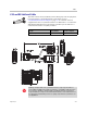
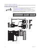
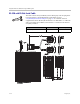

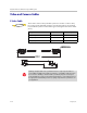
Table Of Contents
- About This Guide
- Contents
- Room Integration
- Setting Up a Room for Video Conferencing
- Integrating Video
- Connecting Polycom Cameras
- Polycom EagleEye HD Camera as the Main Camera up to 30 ft Away
- Polycom EagleEye HD Camera as the Second Camera up to 30 ft Away
- Polycom EagleEye HD Camera as the Main or Second Camera up to 100 ft Away
- Polycom EagleEye 1080 or Sony EVI-HD1 PTZ as the Main or Second Camera
- PowerCam as the Main Camera up to 10 ft Away
- PowerCam as the Second Camera
- PowerCam Plus as the Main Camera up to 10 ft Away
- PowerCam Plus as the Second Camera up to 10 ft Away
- Connecting Sony and ELMO Cameras
- Connecting Vaddio and Canon Cameras
- Connecting Polycom Cameras
- Integrating Audio and Content
- Cables
- Network Cables
- Video and Camera Cables
- S-Video Cable
- BNC to S-Video Cable
- BNC to S-Video Adapter
- DVI to VGA Monitor Cable
- HDMI Monitor Cable
- BNC Monitor Adapter Cable
- Polycom HDX Component Monitor Cable
- HDX Component Video Cable
- DVI-D Monitor Cable
- Component A/V Monitor Cable
- HDCI Analog Camera Cable
- HDCI Digital Camera Cable
- HDCI Camera Break-Out Cable
- VCR/DVD Composite Cable
- Composite Video Cable
- PowerCam Plus Primary Cable
- HDCI PowerCam Cable
- HDCI PowerCam Plus Adapter Cable
- HDCI VISCA Adapter Cable
- HDCI Polycom EagleEye 1080 Camera Cable
- HDCI Polycom EagleEye View Camera Cable
- HDCI Sony VISCA Adapter Cable
- HDCI EagleEye 1080 or Sony Adapter Cable
- PowerCam Primary Camera Cable
- PowerCam Break-Out Cable
- PowerCam Plus/VISCA Control Cable
- Audio Cables
- Serial Cables
- Straight-Through Serial Cable
- Using the API
- System Commands
- About the API Commands
- !
- abk (deprecated)
- addrbook
- addressdisplayedingab
- advnetstats
- alertusertone
- alertvideotone
- all register
- all unregister
- allowabkchanges
- allowcamerapresetssetup
- allowdialing
- allowmixedcalls
- allowusersetup
- amxdd
- answer
- areacode
- audiometer
- audiotransmitlevel
- autoanswer
- autoshowcontent
- backlightcompensation
- basicmode
- bri1enable, bri2enable, bri3enable, bri4enable
- briallenable
- button
- calendardomain
- calendarmeetings
- calendarpassword
- calendarplaytone
- calendarregisterwithserver
- calendarremindertime
- calendarresource
- calendarserver
- calendarshowpvtmeetings
- calendarstatus
- calendaruser
- calldetail
- calldetailreport
- callencryption (deprecated)
- callinfo
- callstate
- callstats
- camera
- cameradirection
- camerainput
- chaircontrol
- cmdecho
- colorbar
- configchange (deprecated)
- configdisplay
- configparam
- configpresentation
- confirmdiradd
- confirmdirdel
- contentauto
- contentsplash
- country
- cts
- daylightsavings
- dcd
- dcdfilter
- defaultgateway
- dhcp
- dial
- dialchannels
- dialingdisplay
- diffservaudio, diffservfecc, diffservvideo
- directory
- display (deprecated)
- displayglobaladdresses
- displaygraphics
- displayipext
- displayipisdninfo (deprecated)
- displayparams
- dns
- dsr
- dsranswer
- dtr
- dualmonitor
- dynamicbandwidth
- e164ext
- echo
- echocanceller
- enablefirewalltraversal
- enablekeyboardnoisereduction
- enablelivemusicmode
- enablepvec
- enablersvp
- enablesnmp
- encryption
- exit
- exportdirectory
- farcontrolnearcamera
- farnametimedisplay
- flash
- gabk (deprecated)
- gabpassword
- gabserverip
- gaddrbook
- gatekeeperip
- gatewayareacode
- gatewaycountrycode
- gatewayext
- gatewaynumber
- gatewaynumbertype
- gatewayprefix
- gatewaysetup
- gatewaysuffix
- gdsdirectory
- gendial
- gendialtonepots (deprecated)
- generatetone
- get screen
- getcallstate
- getconfiguredipaddress
- gmscity
- gmscontactemail
- gmscontactfax
- gmscontactnumber
- gmscontactperson
- gmscountry
- gmsstate
- gmstechsupport
- gmsurl
- h239enable
- h323name
- h331audiomode
- h331dualstream
- h331framerate
- h331videoformat
- h331videoprotocol
- hangup
- history
- homecallquality
- homemultipoint (deprecated)
- homerecentcalls
- homesystem
- homesystemname
- hostname
- importdirectory
- ipaddress
- ipdialspeed
- ipisdninfo
- ipprecaudio, ipprecfecc, ipprecvideo
- ipstat
- isdnareacode
- isdncountrycode
- isdndialingprefix
- isdndialspeed
- isdnnum
- isdnswitch
- keypadaudioconf
- language
- lanport
- ldapauthenticationtype
- ldapbasedn
- ldapbinddn
- ldapdirectory
- ldapntlmdomain
- ldappassword
- ldapserveraddress
- ldapserverport
- ldapsslenabled
- ldapusername
- linestate
- listen
- localdatetime
- marqueedisplaytext
- maxgabinternationalcallspeed
- maxgabinternetcallspeed
- maxgabisdncallspeed
- maxtimeincall
- mcupassword
- meetingpassword
- monitor1 (deprecated)
- monitor1screensaveroutput
- monitor2 (deprecated)
- monitor2screensaveroutput
- mpautoanswer
- mpmode
- mtumode
- mtusize
- mute
- muteautoanswer
- natconfig
- nath323compatible
- nearloop
- netstats
- nonotify
- notify
- ntpmode
- ntpserver
- numberofmonitors (deprecated)
- numdigitsdid
- numdigitsext
- ocsdirectory
- oobcomplete
- pause
- phone
- pip
- popupinfo
- preset
- pricallbycall
- prichannel
- pricsu
- pridialchannels
- priintlprefix
- prilinebuildout
- prilinesignal
- primarycallchoice (deprecated)
- prinumberingplan
- prioutsideline
- priswitch
- reboot
- recentcalls
- registerall (deprecated)
- registerthissystem
- remotecontrol
- remotemonenable
- requireacctnumtodial
- resetsystem
- roomphonenumber
- rs232 baud, rs232port1 baud
- rs232 mode, rs232port1 mode
- rs366dialing
- rt
- rts
- screen
- screencontrol
- secondarycallchoice (deprecated)
- serialnum
- session
- setaccountnumber
- setpassword
- showpopup
- sleep
- sleeptext
- sleeptime
- snmpadmin
- snmpcommunity
- snmpconsoleip
- snmplocation
- snmpsystemdescription
- snmptrapversion
- soundeffectsvolume
- spidnum
- st
- subnetmask
- sysinfo
- systemname
- tcpports
- techsupport
- teleareacode
- telenumber
- telnetechoeol
- timediffgmt
- typeofservice
- udpports
- unregisterall (deprecated)
- usefixedports
- usegatekeeper
- usepathnavigator
- useroompassword
- v35broadcastmode
- v35dialingprotocol
- v35num
- v35portsused
- v35prefix
- v35profile
- v35suffix
- validateacctnum
- vcbutton
- vcraudioout
- vcrrecordsource
- version
- vgaqualitypreference
- videocallorder
- voicecallorder
- volume
- vortex
- waitfor
- wake
- wanipaddress
- webmonitoring
- webport
- whoami
- Room Design and Layout
- Status Messages
- Polycom HDX 9000 Series Specifications
- Index
Integrator’s Reference Manual for Polycom HDX Systems
2–12 Polycom, Inc.
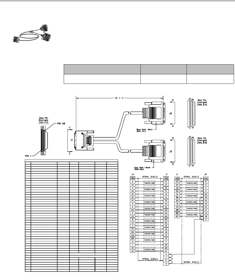
RS-530 with RS-366 Serial Cable
This cable connects a Polycom HDX system to third-party network equipment.
It is used with the V.35/RS-449/RS-530 serial adapter on page
V.35/RS-449/RS-530 Serial Adapter on page 2-7 to connect to network
equipment that has an RS-530/RS-366 interface. It is HD-68M to “Y” DB-25M
and is used with Polycom HDX systems that have a serial network interface
card (NIC) installed.
Length Part Number RoHS Compliant
5 ft (1.65 m) 2457-21263-200 Yes
Peripheral Link V.35 HD-68 Pinout
Notes (direction from V.35 module (DTE))
68 pin Signal Name Signal Type From card Function RS530-DB25 RS366-DB25
Shield V.35/RS449/RS530 7,18,19#
12 Receive Data A Differential in V.35/RS449/RS530 3
11 Receive Data B Differential in V.35/RS449/RS530 16
10 Send Timing A Differential in V.35/RS449/RS530 15
9 Send Timing B Differential in V.35/RS449/RS530 12
29 Data Set Ready (DSR) Single Ended in V.35
28 Request To Send (RTS) Single Ended out V.35
27 Data Terminal Ready (DTR) Single Ended out V.35
34 Digit Present (DPR) Single Ended out RS366 2
24 Abandon Call/Retry (ACR) Single Ended in RS366 3
32 Call Request (CRQ) Single Ended out RS366 4
26 Present Next Digit (PND) Single Ended in RS366 5
21 Data Line Occupied (DLO) Single Ended in RS366 22
14 Receive Timing A Differential in V.35/RS449/RS530 17
13 Receive Timing B Differential in V.35/RS449/RS530 9
8 Terminal Timing A Differential out V.35/RS449/RS530 24
7 Terminal Timing B Differential out V.35/RS449/RS530 11
15 Request To Send (RTS) A Differential out RS449/RS530 4
16 Request To Send (RTS) B Differential out RS449/RS530 19
35** Receive Common Gnd RS449
20 BCD Dial Digit Bit 1 (NB1) Single Ended out RS366 14
19 BCD Dial Digit Bit 2 (NB2) Single Ended out RS366 15
23 BCD Dial Digit Bit 4 (NB4) Single Ended out RS366 16
25 BCD Dial Digit Bit 8 (NB8) Single Ended out RS366 17
2** Signal Ground Gnd V.35/RS366 7,18,19
6 Send Data A Differential out V.35/RS449/RS530 2
5 Send Data B Differential out V.35/RS449/RS530 14
reserved (Ascend select line)
63 Clear To Send (CTS) A Differential in RS449/RS530 5
64 Clear To Send (CTS) B Differential in RS449/RS530 13
61 Data Mode (DM-DSR) A Differential in RS449/RS530 6
62 Data Mode (DM-DSR) B Differential in RS449/RS530 22
65 Receiver Ready (RR-DCD) A Differential in RS449/RS530 8
66 Receiver Ready (RR-DCD) B Differential in RS449/RS530 10
4** Send Common Gnd RS530 7
33 Data Carrier Detect (DCD) Single Ended in V.35
18 Terminal Ready (TR-DTR) A Differential out RS449/RS530 20
17 Terminal Ready (TR-DTR) B Differential out RS449/RS530 23
3 V.35 Cable Connected ground to indicate a V.35 cable is attached 7,18,19*
1 RS449 Cable Connected ground to indicate a RS449 cable is attached 7,18,19^#
22
Distant Station Connected (DSC)
Single Ended in RS366 13
30 Clear To Send (CTS) Single Ended in V.35
31
Ring Indicate (RI) (Incoming Call)
Single Ended in V.35/RS449
reserved (Ascend select line)
68 LOS A Differential out RS530 crypto 18
67 LOS B Differential out RS530 crypto 21
* For V.35, connect pin 3 of 68 pin connector to ground
^For RS449, connect pin 1 of 68 pin connector to ground
#For RS530, connect pins 1 and 3 of 68 pin connector to ground
*** Gndd pinss aree 22,44, 35-60