Ceiling DocCam™ II User Manual ClearOne Communications, Inc.
ii Ceiling DocCam II — Table of Contents 1 Ceiling DocCam II — Introduction Table of Contents Introduction Introduction . . . . . . . . . . . . . . . . . . . . . . . . . . . . . . . . . . . . . . . . . . . . . . . . . . . .1 The Ceiling DocCam™ II is a ceiling-mounted document camera that displays images on monitors, plasma screens, video projectors and videoconferencing systems. It is ideal for presenting or sharing any type of object or document, from detailed images to large blueprints.
2 Ceiling DocCam II — Introduction Ceiling DocCam II — Introduction Unpacking Important safeguards Ensure that you received the following parts: • Read and understand all instructions before using. • Do not operate the Ceiling DocCam II if the power cord is damaged or if the Ceiling DocCam II has been dropped or damaged. A qualified service technician must examine the Ceiling DocCam II before operating. • Do not attempt to take the Ceiling DocCam II apart.
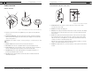
Ceiling DocCam II — Introduction 5 Ceiling DocCam II — Introduction Front and back wall plate connections Product overview Camera enclosure E C B B 15 VDC C Composite Video F D S-video A RS-232 A G E Figure 3. Front and back wall plate A. RJ-45 Connector. The RJ-45 jack connects to the RJ-45 connector on the camera enclosure using a Cat. 5 cable. B. 15 VDC.The 15 VDC power supply jack. D Figure 2. Front and back of camera enclosure and trim ring A. Lens.
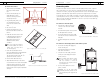
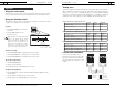
6 Ceiling DocCam II — Introduction Remote 7 Ceiling DocCam II — Installation Installation M Before you install PWR FLIP A The following equipment is needed for proper installation: L DISPLAY K B FREEZE AUTO FOCUS ZOOM IN C CAM LASER D ZOOM OUT J 0 1 2 3 4 5 String or plumb bob • Utility knife • Flathead screwdriver Be sure to check above the ceiling tile where you plan to install the camera to make sure the area is clear and that there is enough room for the Ceiling DocCam II
8 Ceiling DocCam II — Installation 9 Ceiling DocCam II — Installation To mount the camera Connecting cables 1. Attach a string or plumb bob to the ceiling tile with a thumb tack. A single RJ-45 cable connects to the back of the wall plate providing S-video, composite video, power and RS-232 control. The front of the wall plate provides the break-out connections for S-video, composite video, power and RS-232 control.
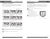
10 Ceiling DocCam II — Installation 11 Ceiling DocCam II — Installation Configuring for remote controls Programming presets The Ceiling DocCam II can be programmed to work with the remotes listed below. DIP switches on the camera enclosure must be configured in order to work with these remotes. See Figure 2 on page 4 for exact location of DIP switches. Use the following diagram to program your Ceiling DocCam II correctly.
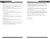
12 Ceiling DocCam II — Operation 13 Ceiling DocCam II — Operation Viewing areas Operation Using your codec remote The only function you can control on the Ceiling DocCam II from your codec remote is the zoom in or zoom out. All other functions must be performed using the ClearOne remote. Viewing area depends on the distance between the ceiling and the table. Use the following tables to determine the maximum and minimum viewing areas of the Ceiling DocCam II for distances of 5.5', 6.5' and 7.5'.
14 Ceiling DocCam II — Troubleshooting Troubleshooting Problem Try this Verify that the Cat. 5 is connected between the RJ-45 jack on the back of the camera module enclosure and the RJ-45 jack on the back of the wall plate. No video image Make sure the provided 15 VDC power supply is plugged into a wall outlet and the 15 VDC jack on the wall plate.
16 Ceiling DocCam II — Appendix 17 Ceiling DocCam II —Appendix Warranty ClearOne Communications, Inc. (Manufacturer) warrants that this product is free of defects in both materials and workmanship.
18 Ceiling DocCam II — Appendix 19 Ceiling DocCam II — Appendix FCC Part 15/ICES-003 Compliance 89/336/EEC "Electromagnetic Compatibility (EMC) Directive": This equipment has been tested and found to comply with the limits for a Class A digital device, pursuant to Part 15 of the FCC rules and Industry Canada ICES-003.These limits are designed to provide reasonable protection against harmful interference when the equipment is operated in a commercial environment.
20 Ceiling DocCam II — Appendix RS-232 control information Note: For best performance of the VISCA commands, set DIP switches to the ClearOne configuration when the camera is connected to the control port of a codec. 21 Ceiling DocCam II — Appendix • Error message When a command or inquiry command could not be executed or failed, an error message is returned instead of the completion message.
22 Ceiling DocCam II — Appendix VISCA Camera-Issued Messages Command List ACK/Completion Messages Command Messages 23 Ceiling DocCam II — Appendix Command Set Command Command Packet Comments Camera Power On 81 01 08 01 01 FF Power on Off 81 01 08 01 00 FF Power off On 81 01 08 02 01 FF Power on Comments Laser Power ACK z0 4y FF (y:Socket No.) Returned when the command is accepted. Completion z0 5y FF (y: Socket No.) Returned when the command has been executed.
24 Ceiling DocCam II — Appendix Command Set CAM _AF Mode Command Normal AF Command Packet Interval AF 81 01 04 57 00 FF 81 01 04 57 01 FF Zoom Trigger AF 81 01 04 57 02 FF Comments Command Set AF Movement Mode CAM_ Gain Active/Interval Time 81 01 04 27 0p 0q 0r 0s FF pq: Movement Time rs: Interval CAM_ZoomFocus Direct 81 01 04 47 0p 0q 0r 0s 0t 0u 0v 0w FF pqrs: Zoom Position tuvw: Focus Position CAM_Initialize Lens 81 01 04 19 01 FF Lens Initialization Start Comp Scan 81 01 04 19 02 F
26 Ceiling DocCam II — Appendix Command Set CAM_Stablizer CAM_Memory CAM_Custom CAM_Display Command Command Packet On 81 01 04 34 02 FF Off 81 01 04 34 03 FF Reset 81 01 04 3F 00 0p FF Set 81 01 04 3F 01 0p FF Recall 81 01 03 3F 01 0p FF Reset 81 01 04 3F 00 7F FF Set Recall 81 01 04 3F 01 7F FF 81 01 04 3F 02 7F FF On 81 01 04 15 02 FF (81 01 06 06 02 FF) 81 01 04 15 03 FF (81 01 06 06 03 FF) Off 27 Ceiling DocCam II — Appendix Comments Command Set Command Vibration Correction
28 Ceiling DocCam II — Appendix Inquiry Command 29 Ceiling DocCam II — Appendix Inquiry Command Command Packet Inquiry Packet Comments 81 09 04 29 FF 90 50 0p 0q 0r 0s FF Inquiry Command Command Packet Inquiry Packet Comments CAM_SpotAE PosInq Camera Power 81 09 08 01 FF 90 50 00 FF Off CAM_ApertureInq 81 09 04 42 FF 90 50 00 00 0p 0q FF pq: X position rs: Y position pq: Aperture Gain 90 50 01 FF On 81 09 04 61 FF 90 50 02 FF On 90 50 00 FF Off On CAM_LR_Reverse ModeInq CAM_F
30 Ceiling DocCam II — Appendix 31 Ceiling DocCam II — Appendix Block Inquiry Command List Lens Control System Inquiry Commands ...
32 Ceiling DocCam II — Appendix 33 Ceiling DocCam II — Appendix Camera Control System Inquiry Commands ...
34 Ceiling DocCam II — Appendix 35 Ceiling DocCam II — Appendix Other Inquiry Commands ...
36 Ceiling DocCam II — Appendix 37 Ceiling DocCam II — Appendix Enlargement Function Query Command ...
38 Ceiling DocCam II — Appendix 39 Ceiling DocCam II — Appendix VISCA Command Setting Values Exposure control Exposure control Shutter Speed NTSC PAL 15 10000 10000 14 6000 13 28 dB 6000 0E 4000 3500 12 3000 2500 11 2000 1750 10 1500 1250 0F 1000 1000 0E 725 600 0D 500 0C 0E 7 10.5 dB 0D 6 9 dB 24 dB 0C 5 7.5 dB F1.6 22 dB 0B 4 6 dB 1B F1.6 20 dB 0A 3 4.5 dB 1A F1.6 18 dB 09 2 3 dB 19 F1.6 16 dB 08 1 1.5 dB 18 F1.
40 Ceiling DocCam II — Appendix Zoom Ratio and Zoom Position (for reference) 41 Ceiling DocCam II — Appendix Lens Control 0000 x25-NTSC Zoom Ratio Optical Zoom x25 Lens Position Data x1 0000 x2 1781 Digital Zoom Ratio x25-PAL Digital Zoom Position Data Digital Zoom Position Data x1 4000 4000 x2 5E00 5E80 x3 6800 6880 x3 213B x4 6D00 6DC0 x4 2752 x5 7000 70C0 x5 2BB3 x6 7200 72C0 x6 2F03 x7 7380 7440 x7 315D x8 7480 7540 x8 3364 x9 7580 7600 x9 34FF x10