User’s Guide for the Polycom Mobile Responder October 2006 Edition 3725-23487-003/A VideoVoiceDataWeb
Trademark Information Polycom®, the Polycom logo design, and SoundStation VTX 1000® are registered trademarks of Polycom, Inc. Mobile Responder™, People+Content™, PowerCam™, Pro-Motion™, and VSX™ are trademarks of Polycom, Inc. in the United States and various other countries. All other brand and product names are trademarks or registered trademarks of their respective companies. Patent Information The accompanying product is protected by one or more U.S.
About this Guide This guide provides users of the Polycom® Mobile Responder™ system with information about how to set up the Mobile Responder, tips about using the system, and troubleshooting information. For additional information about the Polycom Mobile Responder, refer to these other documents: • Quick Setup for the Polycom Mobile Responder, which describes how to quickly identify the parts of the system, connect equipment to the connection panel, and power on the system.
User’s Guide for the Polycom Mobile Responder iv
Contents 1 Introducing the Polycom Mobile Responder . . . . . . . . . . . . . . . . 1-1 System Components . . . . . . . . . . . . . . . . . . . . . . . . . . . . . . . . . . . . . . . . . . . . 1-2 Key Features . . . . . . . . . . . . . . . . . . . . . . . . . . . . . . . . . . . . . . . . . . . . . . . . . . . 1-3 Physical Attributes . . . . . . . . . . . . . . . . . . . . . . . . . . . . . . . . . . . . . . . . . . 1-3 Built-in Components . . . . . . . . . . . . . . . . . . . . . . . . . . . . . . . . . .
User’s Guide for the Polycom Mobile Responder vi
1 Introducing the Polycom Mobile Responder The Polycom Mobile Responder is a complete video conferencing system packaged in a portable case. Based on Polycom’s VSX 8000 system, the Mobile Responder includes a built-in display, camera, microphone, speaker, and IP network interface. Because it is transportable and quick to set up, the Mobile Responder is ideal for anyone who wants to accomplish more while on the road or in the field.
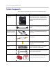
User’s Guide for the Polycom Mobile Responder System Components These standard components come with the Polycom Mobile Responder: Name Component Description Polycom Mobile Responder The Polycom Mobile Responder is a transportable video conferencing system. The system offers built-in components, such as a display and camera, a connection panel that enables you to connect additional components, and the VSX 8000 user interface.
Introducing the Polycom Mobile Responder You may also add optional components to your Mobile Responder. For example, you can add: • QBRI, PRI, or V.
User’s Guide for the Polycom Mobile Responder • Lid-mounted speaker • Convenient connection panel for connecting external devices, such as a VCR, laptop, or projector.
2 Setting Up and Using the Polycom Mobile Responder The Polycom Mobile Responder was specifically designed to be easy to set up. Many components, such as the camera and display, are built in, so they’re ready to use at a moment’s notice. If you want to add optional components, the connection panel is right inside the case so you can easily connect any cables you need. Once all your components are set up and you power on the Mobile Responder, you’re ready to use the system.
User’s Guide for the Polycom Mobile Responder Identifying System Parts The following illustration identifies the major parts of the Mobile Responder: 17” display Speaker Camera Power interlock switch (turns off power to lid when lid is closed) IR activity indicator LCD buttons: - Power - Up/Display Mode - Down - Select - Menu Side panel (Power button and connector) Connection panel IR receiver Accessory storage compartment Microphone Attaching the Remote Tether To operate the Mobile Responder, yo
Setting Up and Using the Polycom Mobile Responder To attach the remote tether: 1. Peel the backing off one side of the remote tether, and stick it to the inside wall of the accessory storage compartment: By sticking the remote tether to the inside wall of the accessory storage compartment: — The remote tether remains out of the way of items stored inside the compartment. — You can close the Mobile Responder lid without damaging the display or any other components. 2.
User’s Guide for the Polycom Mobile Responder Connecting Equipment to the Connection Panel The Mobile Responder comes with built-in components, including the camera, microphone, display, and speaker. However, if you want to connect additional components to the system, you can do so very easily by using the connection panel. The following illustration shows some of the optional components you can connect to the connection panel. To purchase optional components, contact your Polycom distributor.
Setting Up and Using the Polycom Mobile Responder This connector... Enables you to... Mic In Connect to an external speaker system, headset, or handset. If you connect a device to the Mic In connector, the Mobile Responder’s internal microphone is deactivated. The internal microphone reactivates as soon as you disconnect the external device from this connector. Line Out Connect to a sound system or a headset.
User’s Guide for the Polycom Mobile Responder This connector... Camera 1 Control and Camera 1 In Enables you to... 1 1 Connect to an external camera, such as a Polycom PowerCam or PowerCam Plus. Alternatively, you can use the Camera 1 In connector to connect video from a VCR or DVD player. If you connect an external NTSC camera to the Camera 1 In connector, the Mobile Responder’s internal camera remains activated.
Setting Up and Using the Polycom Mobile Responder 2. Using a slotted screwdriver, open the back panel of the Mobile Responder by rotating the lock 180 degrees: 3. Remove the back panel. 4. Using a Phillips screwdriver, unscrew the plate inside, and remove it as well. 5. Slide in the network module all the way to the back: 6. Tighten the screws on each side of the network module. 7. If you plan to use to the optional network interface right away, attach the network cable to the module.
User’s Guide for the Polycom Mobile Responder Powering On the Mobile Responder After you have connected any additional equipment to the Mobile Responder, you can connect the power cable and then power on the Mobile Responder. The power consumption for the Mobile Responder is listed in the following table: During this time... The power consumption is... Startup 0.5 amp to 1 amp @ 100 - 240 VAC Running idle 1.2 amps @ 100 - 240 VAC LAN call 1.2 amps @ 100 - 240 VAC To connect the power cable: 1.
Setting Up and Using the Polycom Mobile Responder Performing Video Conferencing Tasks Because the Mobile Responder is based on Polycom’s VSX 8000 video conferencing system, you can use your Mobile Responder to perform virtually all of the video conferencing tasks that you can perform with a VSX 8000. For example, you can place and end video calls, share data, customize the look and behavior of the system for your particular needs, and so on.
User’s Guide for the Polycom Mobile Responder Restoring System Settings If you reset the VSX 8000 to the factory defaults and delete the system settings, follow these steps to restore the system settings for the Mobile Responder: 1. Press and hold down the button on the remote control while powering on the Mobile Responder. Hold the button until the Polycom logo appears on the screen. 2. Use the remote control to select a language, and then follow the remaining screens in the setup wizard. 3.
Setting Up and Using the Polycom Mobile Responder On this VSX 8000 screen... System > Admin Settings > Audio (page 4) Set this field... To this setting...
User’s Guide for the Polycom Mobile Responder 2 - 12
3 Troubleshooting This chapter presents problems, likely causes, and corrective actions for the Mobile Responder. Problems are organized by category to help you troubleshoot them quickly. You can find additional troubleshooting information in the Administrator’s Guide for the VSX Series, which is available on the VSX Series documentation CD that comes with the Mobile Responder or at www.polycom.com/videodocumentation.
User’s Guide for the Polycom Mobile Responder Power Symptom Problem Corrective Action The system does not start or respond in any way. The Power button is off. 1. Press the Power button located inside the side panel to the on position. 2. Wait one to two minutes for the system to completely power on. The power cable is not connected. Make sure the power cable is connected to a power outlet, and that the power cable is seated securely both in the outlet and in the Mobile Responder.
Troubleshooting System Components Symptom Problem Corrective Action The screen is blue. You connected an external PAL camera to the Camera 1 In 1 connector, which deactivates the internal camera. Do one of the following: • If you plan to use an external PAL camera all of the time, go to System > Admin Settings > Cameras and set the Primary Camera setting to 1.
User’s Guide for the Polycom Mobile Responder Symptom Problem Corrective Action The people at the far site cannot hear you or you cannot hear them. The people at your site or at the far site are too far from the microphone. Move closer to the microphone or turn up the volume using the remote control. Also, if you are using an external microphone, check that the microphone is correctly connected. The microphone at your site or at the far site is muted. Make sure all microphones are not muted.
Troubleshooting Contacting Technical Support To contact Polycom Technical Support, go to www.polycom.com/support. You can enter information about your system and ask a question or describe your problem. When contacting Technical Support, be sure you know the serial number of your system. The serial number is located on the inside of the side panel cover.
User’s Guide for the Polycom Mobile Responder 3-6
Safety and Regulatory Notices Important Safeguards Read and understand the following instructions before using the system: • Close supervision is necessary when the system is used by or near children. Do not leave unattended while in use. • Only use electrical extension cords with a current rating at least equal to that of the system. • Always disconnect the system from power before cleaning and servicing and when not in use. • Do not spray liquids directly onto the system when cleaning.
User’s Guide for the Polycom Mobile Responder License Restrictions THE SOFTWARE PROGRAMS CONTAINED OR DESCRIBED HEREIN ARE CONFIDENTIAL INFORMATION AND PROPRIETARY PRODUCTS OF POLYCOM, INC. OR ITS LICENSORS. Buyer shall not sublicense or otherwise distribute any of the Subject Programs except to End Users and/or resellers who have entered into a Sublicense Agreement.
Safety and Regulatory Notices Warranty Information EXCLUSIONS. POLYCOM WILL NOT BE LIABLE UNDER THIS LIMITED WARRANTY IF ITS TESTING AND EXAMINATION DISCLOSE THAT THE ALLEGED DEFECT OR MALFUNCTION IN THE PRODUCT DOES NOT EXIST OR RESULTS FROM: • FAILURE TO FOLLOW POLYCOM'S INSTALLATION, OPERATION, OR MAINTENANCE INSTRUCTIONS. • UNAUTHORIZED PRODUCT MODIFICATION OR ALTERATION. • UNAUTHORIZED USE OF COMMON CARRIER COMMUNICATION SERVICES ACCESSED THROUGH THE PRODUCT.
User’s Guide for the Polycom Mobile Responder Regulatory Notices Warning This is a Class A product. In a domestic environment, this product may cause radio interference in which case the user may be required to take adequate measures. USA and Canadian Regulatory Notices FCC Notice Class A Digital Device or Peripheral This equipment has been tested and found to comply with the limits for a Class A digital device, pursuant to Part 15 of the FCC Rules.
Safety and Regulatory Notices Regulatory Notices The system can accept AC voltages between 98 and 250 VAC, 7A 50-60 Hz. FCC compliant telephone cords and modular plugs are provided with this equipment. This equipment is designed to be connected to the telephone network or premises’ wiring using a compatible modular jack, which is Part 68 compliant. See installation instructions for details.
User’s Guide for the Polycom Mobile Responder Regulatory Notices Declaration of Conformity: Hereby, Polycom Ltd. declares that this Mobile Responder is in compliance with the essential requirements and other relevant provisions of Directive 1999/5/EC. Konformitetserklæring: Hermed erklærer Polycom Ltd., at indestående Mobile Responder er i overensstemmelse med de grundlæggende krav og de relevante punkter i direktiv 1999/5/EF. Konformitätserklärung: Hiermit erklärt Polycom Ltd.
Safety and Regulatory Notices Regulatory Notices Special Safety Instructions Follow existing safety instructions and observe all safeguards as directed. Installation Instructions Installation must be performed in accordance with all relevant national wiring rules. Plug Acts as Disconnect Device The socket outlet to which this apparatus is connected must be installed near the equipment and must always be readily accessible.
User’s Guide for the Polycom Mobile Responder Safety and Regulatory Notices - 8
Index A accessory storage compartment attaching remote tether to 2-3 location of 2-2 tips 2-9 adapter, S-video to RCA 1-2, 3-3 Audio In connector 2-5 audio, troubleshooting 3-3, 3-4 B back panel, removing 2-7 C cable LAN 1-2 power 1-2 VGA 1-2 camera connecting 2-6 location of 2-2 troubleshooting 3-3 components built-in 1-3 optional 1-3 standard 1-2 composite video 1-2, 3-3 computer, connecting 2-5 Conference-Link connector 2-6 connection panel connecting equipment to 2-4 illustration of 2-5 location of 2-2
User’s Guide for the Polycom Mobile Responder microphone connecting 2-6 location of 2-2 troubleshooting 3-4 Mobile Responder attaching remote tether to 2-3 built-in components 1-3 connecting equipment to 2-4 contacting technical support 3-5 identifying system parts 2-2 introduction 1-1 key features 1-3 physical attributes 1-3 powering on 2-8 restoring system settings 2-10 setting up 2-1 system components 1-2 tips on using 2-9 troubleshooting 3-1 weight of 2-9 monitor, connecting 2-5 N network connecting to
Index video, troubleshooting 3-3 VSX included features 1-4 performing video conferencing tasks 2-9 remote control 1-2 restoring system settings 2-10 Index - 3