
User manual

MGC Hardware and Installation Manual
2-25
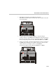
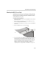
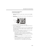
8. To remove the plate from the right side of the MGC unit remove the
appropriate number of functional modules to allow access to the screws.
9. From the inside of the MGC-50, screw the mounting bracket to the side
of the MGC-50, securing the screws with the mounted nuts.
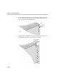
10. Insert the functional modules removed earlier into the MGC-50.
11. Mount the Power Supply module and Main Control Module back in their
place as described in Chapter 5, “Replacing the Main Control Module,”
page 5-18 and “Replacing the Power Supply Module,” page 5-12.
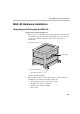
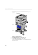
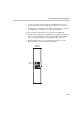
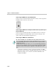
12. Place the MGC-50 in a 19” rack and while supporting it, screw the
mounting brackets to the rack securing it with nuts.
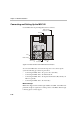
MGC-50
in 19" Rack
M
ounting
Plate
Power
L1
L2
Critical
Major
Minor
L0
CONT
MGC- 50
ACCORD
PWR
OUT
Stby
Fail
Active
Line 6
Line 7
Line 8
Line 3
Line 4
Line 5
Line 1
Line 2
StbyStby
FailFail
ActiveActive
StbyStbyStby
FailFailFail
ActiveActiveActive
Stby
Fail
Active
Stby
Fail
Active
VIDEOVIDEO VIDEOVIDEOAUDIOAUDIOMG-323PRI-8