
User manual


Chapter 4 - Hardware Description
4-2
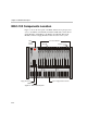
MGC-100 Components Location
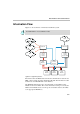
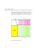
Figure 4-1 shows the front panel of the MGC-100. The front panel provides
access to the Main Control Module, the Functional Modules, and the Power
Supply Modules. Status LEDs on the Main Control Module, Functional
Modules, and Power Supply Modules indicate the status of the system.
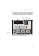
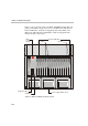
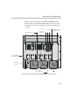
Figure 4-1: MGC-100 front panel
Power Supply Module Handle
Ejectors
LEDs
Floppy Disk Drive
Main
Control
Module
COM Port
Power
L1
L2
L3
Critical
Major
Minor
L0
PWR
IN OUT
CONT
PWR
IN OUT
PWR
IN
OUT
Line A
Line B
Stb y
Fail
Active
Stby
Fail
Active
Stb y
Fail
Active
Stby
Fail
Active
Stby Stby
Fail Fail
Active Active
Stb y
Fail
Active
Stby Stby
Fail Fail
Active Active
Stb y
Fail
Active
Stby Stby
Fail Fail
Active Active
Stby
Fail
Active
Stby
Fail
Active
Stby
Fail
Active
NET-E1
MUX MUX DATA DATA
VIDEO VIDEO VIDEO AUDIOVIDEO AUDIO
Stby
Fail
Active
A
UDIO
A
UDIO
Functional Modules
Line 6
Line 7
Line 8
Line 3
Line 4
Line 5
Line 1
Line 2
Line 6
Line 7
Line 8
Line 3
Line 4
Line 5
Line 1
Line 2
Line 6
Line 7
Line 8
Line 3
Line 4
Line 5
Line 1
Line 2
NET-8NET-8 NET-8
MGC-100